GL-EXP-DIM-CN/GL-EXP-DIMFDB-CN/GL-EXP-DIMFLV-CN/GL-EXP-DIMU-CN/GL-EXP-SW-CN
Crestron Green Light
®
Expansion Module with Cresnet
®
Communication
Installation Guide
Description
The GL-EXP-DIM-CN, GL-EXP-DIMFDB-CN, GL-EXP-DIMFLV-CN, GL-EXP-DIMU-CN,
and GL-EXP-SW-CN are single-channel Crestron Green Light expansion modules that are
controlled with Cresnet communication. They provide control for a variety of lighting loads.
A single module supports 100 to 277 volt loads up to 16 amps.
The Crestron
®
GL-EXP-DIM-CN, GL-EXP-DIMFDB-CN, GL-EXP-DIMFLV-CN,
GL-EXP-DIMU-CN, and GL-EXP-SW-CN share common features and functions and will be
referred to as “GL-EXP-*-CN” except where noted.
The specications for the GL-EXP-*-CN are listed below.
Specications
SPECIFICATION DETAILS
Load Ratings
Channels
Load Rating
Dimmed Load Types
Switched Load Types
1
16 A
GL-EXP-DIM-CN:
LED, incandescent, neon/cold cathode, magnetic
low-voltage, 2-wire dimmable uorescent
GL-EXP-DIMU-CN:
Incandescent, LED, electronic low-voltage, magnetic
low-voltage, neon/cold cathode, 2-wire uorescent
GL-EXP-DIMFDB-CN:
3-wire electronic uorescent dimming ballasts
GL-EXP-DIMFLV-CN:
LED, incandescent, uorescent, magnetic low-voltage,
electronic low-voltage, neon/cold cathode,
high-intensity discharge (HID), motor
GL-EXP-SW-CN:
LED, incandescent, uorescent, magnetic low-voltage,
electronic low-voltage, neon/cold cathode,
high-intensity discharge (HID), motor
Input Voltage 100 to 277 Vac, 50/60 Hz
Environmental
Temperature
Humidity
32° to 104 °F (0° to 40 °C)
10% to 90% RH (noncondensing)
Weight 3.4 lb (1.6 kg)
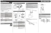
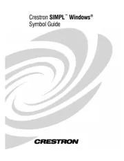
The dimensions for the GL-EXP-*-CN are shown in the following illustrations.
GL-EXP-*-CN Dimensions
5 13/16 in
(147 mm)
5/16 in
(9 mm)
8 5/16 in
(211 mm)
7 5/16 in
(186 mm)
8 5/8 in
(219 mm)
8 3/4 in
(223 mm)
1/2 in
(13 mm)
6 3/8 in
(163 mm)
(2x) Ø3/16 in
(5 mm)
(2x)
Ø3/18 in
(10 mm)
(2x) Ø1/4 in
(7 mm)
5 1/16 in
(129 mm)
3 13/16 in
(81 mm)
2 in
(52 mm)
Typ
1 13/16 in
(46 mm)
3 1/16 in
(78 mm)
(1-1/2 in
(39 mm)
Double ring knockout for 1/2 in and 3/4 in
conduit Ø.875 and Ø1.125 in after knockout
removal (typ).
Additional Resources
Visit the product page on the Crestron website (www.crestron.com)
for additional information and the latest rmware updates. Use a QR
reader application on your mobile device to scan the QR image.
IMPORTANT SAFEGUARDS
When using electrical equipment, basic safety precautions should always be followed
including the following:
READ AND FOLLOW ALL SAFETY INSTRUCTIONS.
• Do not use outdoors.
• Do not mount near gas or electric heaters.
• Equipment should be mounted in locations and at heights where it will not be
subjected to tampering by unauthorized personnel.
• The use of accessory equipment not recommended by the manufacturer may cause
an unsafe condition.
• Do not use this equipment for other than its intended use.
• All servicing should be performed by qualied service personnel.
• If any Emergency Circuits are fed or controlled from this panel, it must be located
electrically where fed from a UPS, generator, or other guaranteed source of power
during emergency and power outage situations.
SAVE THESE INSTRUCTIONS.
Installation
WARNING: To avoid re, shock, or death, turn off the power at the circuit breaker(s) or
fuse and test that power is off before wiring!
NOTE: Observe the following points:
• This product must be installed and used in accordance with the appropriate
electrical codes and regulations.
• This product must be installed by a licensed electrician.
• Use 75°C copper wire or better.
NOTE: Before using the GL-EXP-*-CN, ensure the device is using the latest rmware.
Check for the latest rmware for the GL-EXP-*-CN at www.crestron.com/rmware. Load
the rmware onto the device using Crestron Toolbox™ software.
Preparing and Connecting Cresnet, 0-10V, and Override Ports
Strip the ends of the wires approximately 7/16 in (11 mm). Use care to avoid nicking the
conductors. Tighten the connector to 5 in-lb (0.5 to 0.6 N-m). The wire gauge should be
14 to 26 AWG.
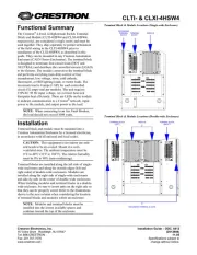
Installation
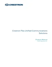
Mount the GL-EXP-*-CN to any vertical surface using four screws. The screws must be
appropriate for the mounting surface.
Installing the GL-EXP-*-CN Module
Mounting surface
(Qty. 4) Mounting
screws, #8 (not
included)
NOTE: To prevent potential heat damage to the drywall, do not mount the
GL-EXP-*-CN directly onto drywall. Mount the GL-EXP-*-CN to a piece of plywood that
is at least 1/2 in (13 mm) thick, and then mount the GL-EXP-*-CN and plywood to the
drywall.
NOTE: To ensure proper ventilation, the device must be installed vertically on a vertical
surface. Install the device with 6 in (153 mm) of clearance from the top and bottom of
the device.
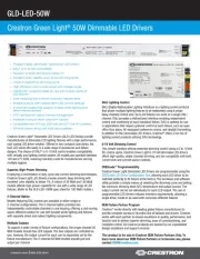
Wiring Diagrams
WARNING: RISK OF SERIOUS PERSONAL INJURY. Turn off power at the circuit
breaker(s) prior to installation. Installing with power on can result in serious personal
injury and damage to the device.
Wire the GL-EXP-*-CN.
1. Use a #2 Phillips screwdriver to remove the cover screws and then remove the cover.
Remove Cover Screws
Cover
screws
2. Wire the device as shown below. An additional LINE, NEUT, and GND connection is
supplied for power to pass through. Keep the following in mind while wiring:
• Wires should be 10 to 24 AWG.
• Wires should be stripped to 5/16 in (8 mm).
• Tighten the terminal screws to 4.5 in-lbs (0.5 Nm).
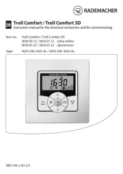
Wire the GL-EXP-DIM-CN
Pass-through to
additional
module
From circuit
breaker
To dimmed
load
From
Override
switch
From
Cresnet