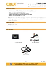
CRUX RVCCH-75 Manual


Læs gratis den danske manual til CRUX RVCCH-75 (3 sider) i kategorien Ikke kategoriseret. Denne vejledning er vurderet som hjælpsom af 16 personer og har en gennemsnitlig bedømmelse på 4.8 stjerner ud af 8.5 anmeldelser. Har du et spørgsmål om CRUX RVCCH-75, eller vil du spørge andre brugere om produktet?

Side 1/3
RVCCH-75
Rear View with VIM Integration Interface and Lip Mount Camera
for Chrysler, Dodge & Jeep Vehicles with MyGig Radio
R
INTERFACING SOLUTIONS
Sightline
Multi View Integration
Crux Interfacing Solutions • 21541 Nordhoff St., Unit C, Chatsworth, CA 91311
phone: (818) 609-9299 • fax: (818) 996-8188 • www.cruxinterfacing.com
rev.021120
1 of 3
Acvates Mygig radio for enabling video features.
Spare re mount camera included.
Interface includes Audio / Video Input to connect an extra A/V source.
Automacally switches to Rear-view when car is in Reverse mode.
Supports vehicles with manual transmission but does not supply +12V Reverse Trigger. Camera power
must be tapped from the +12V reverse light wire instead.
Plug & Play Installaon.
PRODUCT FEATURES:
PARTS INCLUDED:
RVCCH-75 Module RVCCH-75 Harness CUL-03 Lip Mount Camera
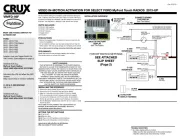
INSTALLATION DIAGRAM:
WHITE Wire
Parking Guideline
DP
ON
DIP
SWITCH
LED* *LED RED = Power ON Status
LED BLUE = Data Bus ON Status
Regulator
20 Ft. Coax Cable
8-Pin Molex
Represents Solder Joint
TO RADIO
WHITE
22-PIN
(MALE)
GRAY
22-PIN
(MALE)
WHITE
22-PIN
(FEMALE)
GRAY
22-PIN
(FEMALE)
TO FACTORY
HARNESS
GREEN WIRE
ACTIVATE VIDEO BYPASS
A/V OUT
A/V INPUT
To Source Ground
(ground wire)
(not chassis ground)
WHITE Wire*
(Camera Power Output
+12V 250mA)
RED Wire
Tape O
(Not Used)
CUL-03 Camera
Included
*White wire does not supply Reverse Trigger on Manual Transmissions.
Camera power must be connected to factory reverse light wire instead.
Crux Interfacing Solutions • 21541 Nordhoff St., Unit C, Chatsworth, CA 91311
phone: (818) 609-9299 • fax: (818) 996-8188 • www.cruxinterfacing.com
rev.021120
2 of 3
R
INTERFACING SOLUTIONS
Sightline
Multi View Integration
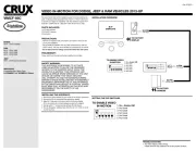
DIP SWITCH SETTINGS:
INSTALLATION INSTRUCTIONS:
INSTALLING THE CAMERA AND INTERFACE
1. Remove the factory radio to gain access to the factory connectors.
2. Plug in the t-harness with WHITE and GRAY connectors. (See wiring diagram on page 1)
3. Set the proper DIP Switch sengs on the RVCCH-75 module. (See chart above)
4. Test the camera for funconality before installing it.
6. Use the WHITE 12V Reverse Output wire to power the camera (see wiring diagram on page 1). DO NOT
connect the red power wire near the camera to the reverse light and insulate this red wire to avoid from
shorng. If the vehicle has a manual transmission, the camera power must be tapped to the +12V reverse light
wire instead. In this case the WHITE 12V Reverse Output wire is not used and should be insulated to avoid
from shorng.
7. Plug in the Yellow male RCA from the camera cable to the Yellow female RCA of the t-harness with white
connectors.
8. Plug in the AV source and test for funconality.
9. Once camera funconallity has been veried. Remove the spate re at the back of the vehicle.
10. Remove the rear panel and drill a 5/8” hole to mount the CUL-03 camera.
11. Connect the power connecon per the diagram on page 1.
12. Connect the video cable of the camera to the extension cord provided.
13. The CUL-03 camera comes with parking guide lines. To disable the partking guide lines cut the thin white wire
loop on the camera cable.
14. Route the cable towards the radio and plug in the yellow RCA to the t-harness.
15. Test the camera and AV input again before re-installing the radio.
DIP SWITCH FUNCTIONS:
DIP 1 = Video in Moon Acvaon ON / OFF
DIP 2 = Rear View Camera ON / OFF
DIP 3 = Set to OFF
DIP 4 = Set to OFF
DIP 5 = CAN Terminaon Radio Side*
DIP 6 = CAN Terminaon Car Side*
RVCCH-75
*DIP 5 & 6
If the radio is having turn-on issues, please try the following:
Aempt 1: Set 5 & 6 to ON
Aempt 2: Set 5 to ON and 6 to OFF
Aempt 3: Set 5 to OFF and 6 to ON
1 2 3 4 5 6
ON
LED INFORMATION:
The RVCCH-75 module has 2 LEDs on the side of the Molex connector that conrms its funconality as follows:
RED LED = Conrms Power
BLUE LED: PULSING = No BUS, Pending Data
OFF = Complete Power Down
SOLID = BUS Recognized
The GREEN wire is used for a non-permanent VIM feature.
Set DIP #1 to OFF and connect the GREEN wire to +12V to
turn on the VIM feature. Use a toggle switch to be able to
turn it ON or OFF.
Rear View with VIM Integration Interface and Lip Mount Camera
for Chrysler, Dodge & Jeep Vehicles with MyGig Radio


Produkt Specifikationer

Mærke: CRUX
Kategori: Ikke kategoriseret
Model: RVCCH-75

Har du brug for hjælp?

Hvis du har brug for hjælp til CRUX RVCCH-75 stil et spørgsmål nedenfor, og andre brugere vil svare dig


Ikke kategoriseret CRUX Manualer
CRUX

CRUX DKGM-16B Manual

3 Januar 2025
CRUX

CRUX ACPBM-77Y Manual

1 Januar 2025
CRUX

CRUX ACPMB-45W Manual

1 Januar 2025
CRUX

CRUX ACPLX-12XW Manual

1 Januar 2025
CRUX

CRUX ACPBM-77X Manual

1 Januar 2025
CRUX

CRUX ACPAD-01 Manual

1 Januar 2025
CRUX

CRUX ACPAD-81Y Manual

1 Januar 2025
CRUX

CRUX ACPBM-77Z Manual

1 Januar 2025
CRUX

CRUX ACPMB-50W Manual

1 Januar 2025
CRUX

CRUX ACPLR-01 Manual

1 Januar 2025

Ikke kategoriseret Manualer

Nyeste Ikke kategoriseret Manualer