CyberPower CPS2200EILCD Manual
CyberPower
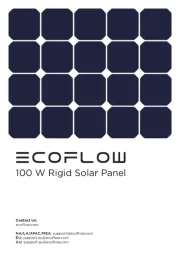
Solpanel
CPS2200EILCD

| Mærke: | CyberPower |
| Kategori: | Solpanel |
| Model: | CPS2200EILCD |
Har du brug for hjælp?
Hvis du har brug for hjælp til CyberPower CPS2200EILCD stil et spørgsmål nedenfor, og andre brugere vil svare dig
Solpanel CyberPower Manualer

19 August 2025

24 September 2024
24 September 2024
23 September 2024

23 September 2024

21 September 2024

7 September 2024

7 September 2024

7 September 2024

6 September 2024
Solpanel Manualer
- Trust
- FOX ESS
- Technaxx
- Xtorm
- Velleman
- Dokio
- Sharp
- Paulmann
- BLUEPALM
- Trina Solar
- EcoFlow
- Jackery
- Enphase
- Viessmann
- Longi
Nyeste Solpanel Manualer

4 November 2025
19 Oktober 2025
18 Oktober 2025
10 Oktober 2025
3 Oktober 2025
29 September 2025
21 September 2025

21 September 2025
21 September 2025
21 September 2025