Eizo ColorEdge CG232W Manual
Læs gratis den danske manual til Eizo ColorEdge CG232W (40 sider) i kategorien overvåge. Denne vejledning er vurderet som hjælpsom af 7 personer og har en gennemsnitlig bedømmelse på 5.0 stjerner ud af 4 anmeldelser. Har du et spørgsmål om Eizo ColorEdge CG232W, eller vil du spørge andre brugere om produktet?
Side 1/40
Important
Please read PRECAUTIONS, this User’s Manual and Setup Manual
(separate volume) carefully to familiarize yourself with safe and effective usage.
• How to Setup
Please read the Setup Manual (separate volume)
•
The latest User's Manual is available for download from our site:
http://www.eizo.com

2
Product specifications may vary depending on the region. Confirm the specifications in the manual written
in the language of the region of purchase.
Copyright© 2008 EIZO NANAO CORPORATION All rights reserved. No part of this manual may be
reproduced, stored in a retrieval system, or transmitted, in any form or by any means, electronic,
mechanical, or otherwise, without the prior written permission of EIZO NANAO CORPORATION.
EIZO NANAO CORPORATION is under no obligation to hold any submitted material or information
confidential unless prior arrangements are made pursuant to EIZO NANAO CORPORATION's receipt
of said information. Although every effort has been made to ensure that this manual provides up-to-date
information, please note that EIZO monitor specifications are subject to change without notice.
Apple, Macintosh, Mac OS and ColorSync are registered trademarks of Apple Inc.
VGA is a registered trademark of International Business Machines Corporation.
VESA is a registered trademark or a trademark of Video Electronics Standards Association in the United
States and other countries.
Windows and Windows Vista are registered trademarks of Microsoft Corporation in the United States and
other countries.
PowerManager and ColorNavigator are trademarks of EIZO NANAO CORPORATION.
ScreenManager, ColorEdge and EIZO are registered trademarks of EIZO NANAO CORPORATION and other
countries.

Notice for this Monitor
3
Notice for this monitor
• Aside from creating documents, viewing multimedia content, and other general purposes, this product is
also suited to applications such as video production, graphics creation and digital photo processing, where
accurate color reproduction is a priority.
• This product has been adjusted specifically for use in the region to which it was originally shipped. If the
product is used outside the region, it may not operate as specified in the specifications.
• This product may not be covered by warranty for uses other than those described in this manual.
• The specifications noted in this manual are only applicable for power cords and signal cables specified by
us.
• Use optional products manufactured or specified by us with this product.
• As it takes about 30 minutes for the performance of electrical parts to stabilize, adjust the monitor 30
minutes or more after the monitor power has been turned on.
• In order to suppress the luminosity change by long-term use and to maintain the stable luminosity, use of a
monitor in lower brightness is recommended.
• When the screen image is changed after displaying the same image for extended periods of time, an
afterimage may appear. Use the screen saver or timer to avoid displaying the same image for extended
periods of time.
• Periodic cleaning is recommended to keep the monitor looking new and to prolong its operation lifetime.
(Refer to "Cleaning" on the next page.)
•
The LCD panel is manufactured using high-precision technology. However, note that the appearance of any
missing pixels or lit pixels does not indicate damage to the LCD monitor.
Percentage of effective pixels : 99.9994% or higher.
•
The backlight of the LCD panel has a fixed life span. When the screen becomes dark or begins to flicker,
please contact your dealer.
• Do not press on the panel or edge of the frame strongly, as this may result in the display malfunction, such
as the interference patterns, etc. If pressure is continually applied to the LCD panel, it may deteriorate or
damage your LCD panel. (If the pressure marks remain on the LCD panel, leave the monitor with a white or
black screen. The symptom may disappear.)
•
Do not scratch or press on the panel with any sharp objects, such as a pencil or pen as this may result in
damage to the panel. Do not attempt to brush with tissues as this may scratch the LCD panel.
•
When the monitor is cold and brought into a room or the room temperature goes up quickly, dew
condensation may occur inside and outside the monitor. In that case, do not turn the monitor on and wait
until dew condensation disappears, otherwise it may cause some damages to the monitor.

4
Notice for this Monitor
Cleaning
NOTE
•
Never use thinner, benzene, alcohol, abrasive cleaners, or other strong solvents, as these may cause
damage to the cabinet or LCD panel.
[LCD Panel]
• The LCD surface can be cleaned with a soft cloth, such as cotton or lens paper.
• If necessary, stubborn stains can be removed by using the provided ScreenCleaner, or moistening
part of a cloth with water to enhance its cleaning power.
[Cabinet]
• To remove stains, wipe the cabinet with a soft, lightly moistened cloth using a mild detergent. Do
not spray wax or cleaner directly into the cabinet. (For details, refer to the manual of the PC.)
To use the monitor comfortably
• An excessively dark or bright screen may affect your eyes. Adjust the brightness of the monitor
according to the environmental conditions.
• Staring at the monitor for a long time tires your eyes. Take a 10-minute rest every hour.

Table of Contents
5
Table of Contents
Cover ............................................................. 1
Notice for this monitor ..........................................
3
Cleaning ................................................................. 4
To use the monitor comfortably ...........................
4
Table of Contents .................................................. 5
1. Introduction ........................................................
6
1-1. Features .............................................................. 6
1-2. Controls and Functions .....................................
7
1-3. Utility Disk ...........................................................
8
1-4. Basic Operation and Functions ........................
9
Basic Operation .....................................................
9
Functions ............................................................. 10
2. Adjusting Screen ............................................. 11
2-1. Setting Screen Resolution ................................11
Compatible Resolutions/Frequencies ................
11
Setting Resolution ................................................
11
2-2. Setting SDI Input Signal ...................................
12
Setting Pseudo Interlace ....................................
12
Expanding Signal Output Range .......................
12
Setting SDI Signal ...............................................
12
Adjusting Sharpness ..........................................
13
Adjusting Display Area .......................................
13
Selecting Effective Bits for a 12-Bit Signal .......
13
2-3. Displaying Screen Correctly
(Analog Input Only) .......................................
14
2-4. Adjusting Color ................................................
17
Simple Adjustment (Switching Color Mode) .....
17
Advanced Adjustments [Adjustment menu] .....
18
2-5. Changing Screen Size Ratio ............................
20
Changing Screen Size Ratio for Input Screen ..
20
2-6. Setting Black Insertion ....................................
22
3. Setting Monitor ................................................ 23
3-1. Setting Power Saving ...................................... 23
Analog Input ........................................................
23
Digital Input ..........................................................
23
3-2. Locking Button Operation ...............................
24
3-3. Setting Power Indicator ...................................
24
3-4. Setting Button Guide .......................................
24
4.Troubleshooting ............................................... 25
5. Reference .........................................................
28
5-1. Attaching an Arm .............................................. 28
5-2. Connecting More than Two PCs
to theMonitor ..................................................
29
5-3. Utilizing USB (Universal Serial Bus) ...............
30
5-4. Specications ................................................... 31
5-5. Glossary ............................................................
35
6. Preset Timing ...................................................37
FCC Declaration of Conformity ..........................
38
Hinweise zur Auswahl des richtigen
Schwenkarms für Ihren Monitor /
Hinweis zur Ergonomie .......................................
39

6
1. Introduction
1. Introduction
Thank you very much for choosing an EIZO Color Monitor.
1-1. Features
•
24.1" wide format LCD
•
Wide color gamut of 97% of Adobe RGB
•
Applicable to HDCP
•
WUXGA(1920 × 1200)display compliant
•
Supports SDI signal inputs (BNC: HD/SD-SDI x 2, or Dual Link SDI x 1)
Resolution : 2048 dots x 1080 lines
•
Supports SDI signal outputs (BNC x 2, Loop-through)
•
Supports DVI / D-SUB signal inputs (DVI-D×1, D-SUB×1)
[Horizontal scanning frequency]
Analog : 26 - 92kHz
Digital : 26 - 78kHz
[Vertical scanning frequency]
Analog : 23.8 - 86Hz
Digital : 23.8 - 61Hz (VGA TEXT: 69 - 71Hz)
[Frame Synchronous mode supported]: 23.8 - 30.5Hz, 47.5 - 61Hz
•
Color Mode function reproduces color gamut and gamma compliant with [EBU/Rec.709/
SMPTE-C] broadcasting standards as well as the [DCI] digital cinema standard (Refer to "2-4.
Adjusting Color" on page 17)
•
Black insertion function for suppressing blur in moving images (Refer to
"2-6. Setting Black
Insertion" on page 22)
•
Setting Pseudo Interlace
(Refer to "2-2.Setting SDI Input Signal" on page 12)
•
The provided "ColorNavigator" calibration software enables you to calibrate monitor
characteristics and generate ICC profiles (for Windows) and Apple ColorSync profiles (for
Macintosh) (Refer to "1-3.Utility Disk" on page 8)
• Smoothing function incorporated for the adjustment of an enlarged image
•
Sharpness function (OutlineEnhancer)
•
Height adjustable stand
• Attaching the "Adjustment Certificate" to describe the grayscale and uniformity characteristics of
the monitor individually

1. Introduction
7
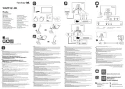
1-2. Controls and Functions
1
2
4 5 6 73
DVI/
D-SUB
SDI
MODE
ENTER
SCAN
TYPE
SIGNAL
FORMAT
SCREEN
SIZE
INFO
DVI/
D-SUB
SDI
MODE
ENTER
SCAN
TYPE
SIGNAL
FORMAT
SCREEN
SIZE
INFO
1. DVI / D-SUB Input Signal Selection button
2. SDI Input Signal Selection button
3. Mode button
4. Enter button
5. Control buttons (Left, Down, Up, Right)
6. Power button
7. Power indicator
Indicator status Operation status
Blue The screen is displayed
Flashing blue (2 times for
each)
When the timer is set for ColorNavigator, notifies that a recalibration is required (for
CAL mode).
Orange Power saving
Off Power off
*
ScreenManager
®
is an EIZO’s nickname of the Adjustment menu.
Adjustment menu
(ScreenManager
®
*)

8
1. Introduction
1-3. Utility Disk
An "EIZO LCD Utility Disk" (CD-ROM) is supplied with the monitor. The following table shows the disk
contents and the overview of the software programs.
Disk contents and software overview
The disk includes software programs for adjustment and User’s Manual. Refer to "Readme.txt" or the
"read me" file on the disk for software startup procedures or file access procedures.
Item Overview For Windows For Macintosh
A “Readme.txt” or “read me” file
√ √
ColorNavigator An application software for calibrating monitor
characteristics and generating ICC profiles (for Windows)
and Apple ColorSync profiles (for Macintosh).
(A PC must be connected to the monitor with the supplied
USB cable.) Refer to the descriotion later.
√ √
Screen Adjustment
Utility
Monitor pattern display software used when adjusting the
image of the analog input signal manually.
√
–
Screen adjustment
pattern files
Used when adjusting the image of the analog signal input
manually. If the Screen Adjustment Utility is not applicable
to your PC, use this pattern files to adjust the image.
√
–
User’s Manual (PDF file)
√ √
To use ColorNavigator
Refer to the corresponding User's Manual on the CD-ROM disk in order to install and use the software.
When using this software, you will need to connect a PC to the monitor with the supplied USB cable.
For more information refer to the "5-3. Utilizing USB (Universal Serial Bus)" (page 30).

1. Introduction
9
1-4. Basic Operation and Functions
Basic Operation
Adjustment menu allows you to adjust screen performance though the main menu and select a Color
mode easily.
DVI/
D-SUB
SDI
MODE
ENTER
SCAN
TYPE
SIGNAL
FORMAT
SCREEN
SIZE
INFO
DVI/
D-SUB
SDI
MODE
ENTER
SCAN
TYPE
SIGNAL
FORMAT
SCREEN
SIZE
INFO
Note
•
The Adjustment menu and the Color Mode menu cannot be displayed at the same time.
1
Entering the Adjustment menu
Press once to display the main menu of the Adjustment menu.
2
Making Adjustments and Settings
1. Select the desired sub menu icon using and press . The sub menu appears.
(Regarding the sub menu, refer to the “Functions” (page 10)).
2. Use to select the desired setting icon and press . The setting menu appears.
3. Use to make all required adjustments and press save the settings.
3
Exiting the Adjustment menu
1. To return to the main menu, select the <Return> icon or press twice, followed by .
2. To exit the Adjustment menu, select the <Exit> icon or press twice, followed by ..
Tips
•
Double clicking
at any time also exits the Adjustment menu.
Adjustment menu
(ScreenManager
®
)
Mode button
Control buttons
(Left, Down, Up, Right)
Power buttonEnter button
Color Mode Menu

10
1. Introduction
Functions
The following table shows all the Adjustment menu's adjustment and setting menus.
Main menu Sub menu SDI DVI D-SUB Reference
Setup Black Insertion
√ √ √
"2-6. Setting Black Insertion" (page
22)
Pseudo Interlace
√
- - "2-2. Setting SDI Input Signal" (page
12)
Range Extension
√
- -
SDI Settings
√
- -
Reset
√ √ √
Screen Auto Adjustment - -
√
"2-3. Displaying Screen Correctly
(Analog Input Only)" (page 14)
Clock - -
√
Phase - -
√
Position - -
√
Resolution - -
√
Range Adjustment - -
√
Screen Size
√ √ √
"2-5. Changing Screen Size Ratio"
(page 20)
Smoothing
√ √ √
Signal Filter - -
√
Switch mode if noise appears on the
screen.
Sharpness
√
- - "2-2. Setting SDI Input Signal" (page
12)
Display Area
√
- -
12bit Mode
√
- -
Color (Custom)
*
1
Black Level
√ √ √
"2-4. Adjusting Color" (page 17)
Brightness
√ √ √
Temperature
√ √ √
Gamma
√ √ √
Saturation
√ √ √
Hue
√ √ √
Gain
√ √ √
Reset
√ √ √
PowerManager On
√ √ √
"3-1. Setting Power Saving" (page 23)
Off
√ √ √
Others Border Intensity
√ √ √
"Set the brightness of the black area
surrounding the displayed image."
(page 21)
Power Indicator
√ √ √
"3-3. Setting Power Indicator" (page
24)
Button Guide
√ √ √
"3-4. Setting Button Guide" (page 24)
Menu Settings Menu Size
√ √ √
Change the size of the menu.
Menu Position
√ √ √
Adjust the menu position.
Menu Off Timer
√ √ √
Set the menu displaying time.
Reset
√ √ √
Return to the factory Default
settings.
*
2
Information Information
√ √ √
Review the Adjustment menu's
settings, model name, serial number
and usage time.
*
3
Language English, German, French,
Spanish, Italian, Swedish,
Chinese(Simplified),
Chinese(Traditional) and
Japanese
√ √ √
Select the Adjustment menu's
language.
*1
The adjustable functions on the <Color> menu depend on the selected Color mode (page 18). The above table shows the sub
menus when the "Custom" mode is selected (See "2-4. Adjusting Color" (page 17)).
*2
The <Setup> settings are not reset.
*3
Due to the inspection on the factory, the usage time may not "0 hour" at shipping.

2. Adjusting Screen
11
2. Adjusting Screen
2-1. Setting Screen Resolution
Compatible Resolutions/Frequencies
For details on compatible resolutions, refer to “Compatible Resolutions/Frequencies” in the Setup
Manual.
Setting Resolution
When you connect the monitor to the PC and find that the resolution is improper, or when you want to
change the resolution, follow the procedure below. When using video editing equipment, refer to the
instruction manual for the equipment.
Windows Vista
1. Right-click the mouse anywhere on the desktop except for icons.
2. From the displayed menu, click "Personalize".
3. On the "Personalization" window, click "Display Settings".
4. On the "Display Settings" dialog, select the "Monitor" tab and select desired resolution in the
"Resolution" field.
5. Click the "OK" button.
6. When a confirmation dialog is displayed, click "Yes".
Windows XP
1. Right-click the mouse anywhere on the desktop except for icons.
2. From the displayed menu, click "Properties".
3. When the "Display Properties" dialog is displayed, click the "Settings" tab and select desired
resolution for "Screen resolution" under "Display".
4. Click the "OK" button to close the dialog.
Mac OS X
1. Select "System Preferences" from the Apple menu.
2. When the "System Preferences" dialog is displayed, click "Displays" for "Hardware".
3. On the displayed dialog, select the "Display" tab and select desired resolution in the "Resolutions"
field.
4. Your selection will be reflected immediately. When you are satisfied with the selected resolution,
close the window.

12
2. Adjusting Screen
2-2. Setting SDI Input Signal
Note
•
These settings can only be made when using the SDI input signal.
The following settings are located on the <Setup> menu of the Adjustment
menu.
Setting Pseudo Interlace
This display method shows the interlaced signals as they are and gives the video a CRT-like display
effect.
Tips
•
<Pseudo Interlace> can be set under these conditions:
-
The input signal is 1080i and the scan type on the <SDI Settings> menu is set to “Interlace”.
-
The input signal is 1080i and the <SDI Settings> menu is set to “Auto” (default setting).
[Procedure]
1. From the <Setup> menu on the Adjustment menu, select <Pseudo Interlace>.
2. Select “On”.
Note
•
When <Pseudo Interlace> is set to “On”, <Black Insertion> cannot be set.
Expanding Signal Output Range
The signal range can be expanded to meet the input signal from 64/1023 - 1019/1023 to 0/1023 -
1023/1023.
[Procedure]
1. From the <Setup> menu on the Adjustment menu, select <Range Extension>.
2. Select “On”
Setting SDI Signal
This setting sets the scan type and signal format.
[Procedure]
1. From the <Setup> menu on the Adjustment menu, select <SDI Settings>.
2. Select “Manual”
3. Select a scan type (Interlace, Progressive, or PsF).
4. Select a signal format (YUV 4:2:2, YUV 4:4:4, or RGB 4:4:4).
Tips
•
The signal format can be set if the SDI signal input is SDI-Dual (A-B) or SDI-Dual (B-A).
•
The signal format is set to YUV 4:2:2 if the SDI input signal is SDI-1 or SDI-2.

2. Adjusting Screen
13
The following settings are located on the <Screen> menu of the Adjustment menu.
Adjusting Sharpness
Emphasizes the outline of the image by emphasizing the color difference
between the pixels composing the image and to improve a sense of quality and
materiality.
Note
•
<Sharpness> may not be adjustable for certain settings. (Refer to " 4. Troubleshooting ").
[Procedure]
1. From the <Screen> menu on the Adjustment menu, select <Sharpness>.
2. Adjust the setting with (0 to 10).
Adjusting Display Area
The display area can be moved when using a 2048-by-1080 input signal.
[Procedure]
1. From the <Screen> menu on the Adjustment menu, select <Display Area>.
2. Adjust the setting with (2 to -2).
Selecting Effective Bits for a 12-Bit Signal
This function selects the effective bits for displaying a 12-bit signal.
[11:2]: Displays a signal formed by the upper 10 bits. (Default setting)
[9:0]: Displays a signal formed by the lower 10 bits.
Tips
•
<12bit mode> can be set under these conditions.
-
The input signal is SDI-Dual (A-B) or SDI-Dual (B-A), and the <SDI Settings> (see previous page)
menu is set to “Manual” and the signal format is set to “RGB4:4:4”.
-
The input signal is SDI-Dual (A-B), SDI-Dual (B-A) or “RGB4:4:4”, and the <SDI Settings> (see
previous page) menu is set to “Auto”.
[Procedure]
1. From the <Screen> menu on the Adjustment menu, select <12bit mode>.
2. Select [11:2] or [9:0] with .

14
2. Adjusting Screen
2-3. Displaying Screen Correctly (Analog Input Only)
Note
•
Allow the LCD monitor to stabilize for at least 30 minutes before making image adjustments.
The monitor displays the digital input image correctly based on its pre-setting data.
The monitor screen adjustment is used to suppress flickering of the screen or adjust screen position
and screen size correctly according to the PC to be used.
To use the monitor comfortably, adjust the screen when the monitor is set up for the first time or when
the settings of the PC in use are updated.
Adjustment Procedure
1
Perform the auto screen adjustment.
1. From the <Screen> menu on the Adjustment menu, select <Auto Adjustment>.
2. Select “Execute”
The Auto Adjustment function begins (showing a running status icon) to adjust flickering,
screen position, and screen size automatically.
Note
•
The Auto Adjustment function is intended for use on the Macintosh and on AT-compatible PC
running Windows. It may not work properly in either of the following cases. It does not work
properly when an image is displayed only on a part of the screen (command prompt window,
for example) or when a black background (wallpaper, etc.) is in use.
• It cannot work correctly using with some graphics cards.
If the screen is not displayed correctly after performing step 1, follow the steps below to adjust the screen.
If the appropriate screen can be made, proceed to 5. Range Adjustment .
2
Prepare the display pattern for the analog display adjustment.
Windows
1. Load the “EIZO LCD Utility Disk” to your PC.
2. Start the “Screen Adjustment Utility” from the startup menu. If it cannot be started, open the
screen adjustment pattern files.
Tips
• For how to open and use the screen adjustment pattern files, refer to “Readme.txt” or the “read
me” file.
Other than Windows
Download the "Screen adjustment pattern files" from our site: http://www.eizo.com.
Tips
•
For details and instructions on opening the “Screen adjustment pattern files”, refer to the “Read
me” file.

2. Adjusting Screen
15
3
Perform the auto size adjustment again with the analog screen adjustment
pattern displayed.
1. Display Pattern 1 in full screen on the monitor using the “Screen Adjustment Utility” or the
screen adjustment pattern files.
2. From the <Screen> menu on the Adjustment menu, select <Auto Adjustment>.
3. Select “Execute”
The Auto Adjustment function begins (showing a running status icon) to adjust flickering,
screen position, and screen size automatically.
4
Adjust by using <Screen> menu in the Adjustment menu
(1)Vertical bars appear on the screen
Use the <Clock> adjustment.Clock> adjustment.
Select the <Clock> and eliminate the vertical bars by using and of the Control buttons.
Do not continuously press the Control buttons, as the adjustment value will change quickly
and make it difficult to locate the most suitable adjustment point. If the horizontal flickering,
blur or bars appear, proceed to <Phase> adjustment as follows.
(2) Horizontal flickering, blurring or bars appear on the screen.
Use the <Phase> adjustment.Phase> adjustment.
Select the <Phase> and eliminate the horizontal flickering, blurring or bars by using and
buttons.
Note
•
Horizontal bars may not completely disappear from the screen depending on the PC.

16
2. Adjusting Screen
(3) The screen position is incorrect.
Use the <Position> adjustment.Position> adjustment.
The correct displayed position of the monitor is decided because the number and the position
of the pixels are fixed. The <Position> adjustment moves the image to the correct position.
Select <Position> and use to adjust the position so that the entire image is
displayed. If vertical bars of distortion appear after finishing the <Position> adjustment, return
to <Clock> adjustment and repeat the previously explained adjustment procedure. ("Clock" =>
"Phase" => "Position")
(4) Screen image is smaller or larger than the actual screen images.
Use the <Resolution> adjustment.Resolution> adjustment.
Adjustment is needed when the input signal resolution and the resolution now being displayed
are different.
Select <Resolution> and confirm if the resolution now being displayed is the same as the
input resolution. If it is not, adjust the vertical resolution using and and adjust the
horizontal resolution using and .
Extra image is displayed due to excessive dots.
A part of image is cut due to short dots.
5
Adjust the output signal range (Dynamic Range) of the signal.
Use the <Range Adjustment> of <Screen> menu.Range Adjustment> of <Screen> menu.
This controls the level of output signal range to display the whole color gradation (256 colors).
[Procedure]
1. Display Pattern 2 in full screen on the monitor using the “Screen Adjustment Utility” or the
screen adjustment pattern files.
2. Choose <Range Adjustment> from the <Screen> menu, and press .
3. "Select “Execute”
Color gradation is adjusted automatically.
4. Close the Pattern 2. When using the “Screen Adjustment Utility”, close the program.

2. Adjusting Screen
17
2-4. Adjusting Color
Simple Adjustment (Switching Color Mode)
Changing the color mode enables you to set the monitor to the appropriate display mode.
Selecting Color Mode
Pressing displays the Color Mode menu at the bottom left of the screen. Each press of changes
through 7 modes.
Press to exit the menu.
->Custom->sRGB->EBU->Rec709->SMPTE-C->DCI->CAL
Tips
•
The Adjustment menu and the Color Mode menu cannot be displayed at the same time.
Color Mode Menu
[EX.]Custom
Settings status of Black
Level, Brightness, Tem-
perature and Gamma
Current Mode
Enter button
DVI/
D-SUB
SDI
MODE
ENTER
SCAN
TYPE
SIGNAL
FORMAT
SCREEN
SIZE
INFO
Mode button
Power button
Control buttons
Color Mode
Selectable Color modes are as follows.
Mode Purpose
Custom Available for the color settings according to your preference.
sRGB Suitable for color matching with sRGB compatible peripherals.
EBU
Suitable for reproducing the color gamut and gamma as set forth by EBU (European Broad-
casting Union) standards.
Rec709
Suitable for reproducing the color gamut and gamma as set forth by the ITU-R Rec. 709
standard.
SMPTE-C Suitable for reproducing the color gamut and gamma as set forth by SMPTE-C standards.
DCI Suitable for reproducing the color gamut and gamma as set forth by DCI standards.
CAL Displays the screen adjusted by calibration software.
Color Adjustment of the Mode Settings
<Black Level>, <Brightness>, <Temperature> and <Gamma> settings can be adjusted on the Color
Mode menu. Select the desired function icon with and adjust with Control buttons.
(Setting(s) of <Temperature> and/or <Gamma> is defined as standard default in some modes.)
Note
•
"CAL" mode can be adjusted only by Calibration Software "ColorNavigator".

2. Adjusting Screen
19
Adjustment Contents
Menu Function Descriptions Adjustable range
Black Level To adjust the black level as desired 0 - 32
Brightness To set the brightness of the screen 0~100%
Tips
•
The values shown in the “%” are available only as reference.
Temperature To set the color temperature 5000K~10000K
in 500 K increments (including 5400K and
9300 K)
Tips
•
The values shown in the Kelvin are available only as a reference tool.
•
While color temperature is adjusted, <Gain> is adjusted automatically according to the
color temperature.
•
If the temperature is set below 5000 K or over 10000 K, the setting of <Temperature>
is turned "Off".
•
If <Gain> is set, the setting of <Temperature> is turned "Off".
Gamma To set the gamma value 1.6 - 2.7
Tips
•
If setting the gamma value, the using the monitor in the digital signal input is
recommended. If using the monitor in the analog input signal, set the gamma value
from 1.8 to 2.2.
Saturation To change the saturation -100~100
Setting the minimum level (-100) turns the
image to the monochrome.
Note
•
This function does not enable to display every color gradation.
Hue To change the flesh color, etc. -100~100
Note
•
This function does not enable to display every color gradation.
Gain To change each color
(red, green and blue)
0~100%
By adjusting the red, green and blue color
tones for each mode, custom colors can be
defined. Display a white or gray background
image and adjust the <Gain>.
Tips
•
The values shown in the “%” are available only as reference.
•
The <Temperature> setting invalidates this setting. The <Gain> setting varies with
color temperature.
Note
•
This function does not enable to display every color gradation.
Reset To return the color settings to the
default settings
Select the <Reset>.

20
2. Adjusting Screen
2-5. Changing Screen Size Ratio
The screen size ratio can be selected using the <Screen Size> function on the <Screen> menu.
Changing Screen Size Ratio for Input Screen
-> Select the <Screen Size>.
Select the <Screen Size> in the <Screen> menu and select the screen size by using and
.
When using DVI/D-SUB input signal
Mode Function
Enlarged Displays the picture on the screen in full, irrespective of the picture's resolution.
Since the vertical resolution and horizontal resolution are enlarged at same rates,
some horizontal or vertical image may disappear.
Normal Displays the picture on the screen using the same resolution of the input signal.
Normal
Enlarged
(Default Setting)
When using SDI input signal (input signal NTSC or PAL)
Mode Function
Dot by Dot Displays the picture on the screen using the same resolution of the input signal.
4:3 Displays the input video expanded to a vertical resolution of 1080 while maintaining
the aspect ratio to 4:3 (horizontal: vertical).
16:9 Displays the input video expanded to a vertical resolution of 1080 while maintaining
the aspect ratio to 16:9 (horizontal: vertical).
Letter Box Displays the letter box input video expanded to a vertical resolution of 1080 while
maintaining the aspect ratio.
Dot by Dot
4:3
(Default Setting)
16:9
16:9
Letter Box
Letter Box

2. Adjusting Screen
21
When using SDI input signal (input signal 720p)
Mode Function
Dot by Dot Displays the picture on the screen using the same resolution of the input signal.
Enlarged Displays the input video expanded to a vertical resolution of 1080 while maintaining
the aspect ratio.
Dot by Dot
Enlarged
(Default Setting)
Enlarged
(Default Setting)
The setting must be adjusted in the following instances after changing the screen size ratio.
Smooth the blurred texts of the enlarged screen.
Switch the <Smoothing> setting.Smoothing> setting.
Select the suitable level from 1 - 5 (Soft - Sharp).
Select <Smoothing> in the <Screen> menu and adjust by using the right and left switches.
Note
•
Smoothing setting may not be required depending on the display resolution. (You cannot
choose the smoothing icon.)
Set the brightness of the black area surrounding the displayed image.
Set the <Border Intensity>.
In “Normal” or “Enlarged” mode, the outer area (border) may appear black.
Select <BorderIntensity> in the <Others> menu and adjust by using .
Border

22
2. Adjusting Screen
2-6. Setting Black Insertion
This setting inserts a black screen to suppress blur when showing moving images.
[Procedure]
1. From the <Setup> menu on the Adjustment menu, select <Black Insertion>.
2. Select “On”
Note
•
The brightness may drop when set to “On”.
•
When set to “On”, the screen may flicker if the DVI/D-SUB input signal exceeds the frame sync
frequency range.
•
When set to “On”, the brightness will not change even if set to 45% or more.

3. Setting Monitor
23
3. Setting Monitor
3-1. Setting Power Saving
The <PowerManager> menu in the Adjustment menu enables to set the power saving.
Note
• Do your part to conserve energy, turn off the monitor when you are finished using it. Turning off the
main power switch or unplugging the power cord completely shuts off power supply to the monitor.
• Devices connected to the USB port (upstream and downstream) work when the monitor is in power
saving mode or when the power button of the monitor is Off. Therefore, power consumption of the
monitor varies with connected devices even in the power saving mode.
• When using ColorNavigator, turning of the power saving function is recommended.
Analog Input
This monitor complies with the "VESA DPMS".
[Procedure]
1. Set the PC's power saving settings.
2. Select "On" from the <PowerManager> menu.
[Power Saving System]
PC Monitor Power Indicator
ON Operation Blue
Power saving
STAND-BY
SUSPEND
OFF
Power saving Orange
[Power Resumption Procedure]
Operate the mouse or keyboard to return to a normal screen.
Digital Input
• DVI: This monitor complies with the DVI DMPM standard.
• SDI: This monitor complies with our original power saving function “SDI”.
[Procedure]
1. Set the PC's power saving settings.
2. Select "On" from the <PowerManager> menu.
[Power Saving System]
The monitor enters the power saving mode in five seconds in connection with the PC setting.
PC or Video Editing Equipment Monitor Power Indicator
ON Operation Blue
Power saving Power saving Orange
[Power Resumption Procedure]
Operate the mouse or keyboard to return to a normal screen.

24
3. Setting Monitor
3-2. Locking Button Operation
Use the "Adjustment Lock" function to prevent any accidental changes.
Buttons that can be locked
•
(Enter button) / Adjustments/settings using
•
(Mode button)
Buttons that cannot be locked
•
(DVI/D-SUB Input Signal Selection button)
•
(SDI Input Signal Selection button)
•
(Power button)
•
(Control buttons)
[How to lock]
1. Press to turn off the monitor.
2. Press again while pressing .
The screen is displayed with the adjustment lock.
[How to unlock]
1. Press to turn off the monitor.
2. Press again while pressing .
The screen is displayed with the adjustment lock released.
3-3. Setting Power Indicator
The brightness of the power indicator (blue) when the screen is displayed can be adjusted (default
setting is set to light up when power is turned on, and brightness is set to 4).
[Procedure]
1. Select <Power Indicator> in the Adjustment menu <Others> menu.
2. Set the brightness with (Off or 1 to 7).
3-4. Setting Button Guide
The Button Guide can be changed between show/hide (default setting is set to show the Button Guide).
[Procedure]
1. Select <Button Guide> in the Adjustment menu <Others> menu.
2. Select "On" or "Off".

4.Troubleshooting
25
4.Troubleshooting
If a problem still remains after applying the suggested remedies, contact your local dealer.
•
No-picture problems : See No.1 - No.2
•
Imaging problems : See No.3 - No.16
•
Other problems : See No.17 - No.21
•
USB problems : See No.22
Problems Possible cause and remedy
1. No picture
•
Power indicator does not light.
•
Check whether the power cord is connected correctly. If
the problem persists, turn off the monitor, and then turn
it on again a few minutes later.
•
Turn the main power switch on.
•
Press
.
•
Power indicator is lighting blue.
•
Set each adjusting value in <Brightness> or <Gain> to
higher level (page 18).
•
Power indicator is lighting orange.
•
Switch the input signal with or .
•
Operate the mouse or keyboard.
•
Check whether the PC is turned on.
•
Check whether the signal cable is connected properly.
2. The message below appears.
This message appears when the signal is not input
correctly even when the monitor functions properly.
•
This message appears when no signal is input.
(This is displayed for about 40 seconds)
•
The message shown left may appear, because some
PCs do not output the signal soon after power-on.
•
Check whether the PC is turned on.
•
Check whether the signal cable is connected properly.
•
Switch the input signal with or .
•
The message below shows that the input signal is out of
the specified frequency range. (Such signal frequency is
displayed in red.)
Example:
•
Check whether the signal setting of your PC matches
the resolution and the vertical frequency settings for the
monitor (page 11).
•
Reboot the PC.
•
Select an appropriate display mode using the graphics
board’s utility. Refer to the manual of the graphics board
for details.
fD: Dot Clock
(Displayed only when the digital signal inputs)
fH: Horizontal Frequency
fV: Vertical Frequency
3. Display position is incorrect.
•
Move the image to the correct position using the
<Position> adjustment. (page 16).
•
If the problem persists, use the graphics board’s utility if
available to change the display position.

26
4.Troubleshooting
Problems Possible cause and remedy
4. Screen image displayed is smaller or larger than the
actual screen image.
•
Adjust the resolution using <Resolution> so that the
input signal resolution equals the resolution in the
resolution adjustment menu (page 16).
5. Vertical bars appear on the screen or a part of the image
is flickering.
•
Adjust using <Clock> (page 15).
6. The characters and images have several vertical bars on
their right side.
•
Adjust the characters and images using the
<Signal Filter>.
7. Whole screen is flickering or blurring.
•
Adjust using <Phase> (page 15).
8. Characters are blurred.
•
Adjust using <Smoothing> (
page 21).
9. Upper part of the screen is distorted as shown below.
•
This is caused when both composite sync (X-OR)
signal and separate vertical sync signal are input
simultaneously. Select either composite signal or
separate signal
10.The screen is too bright or too dark.
•
Adjust <Brightness>. (The LCD monitor backlight has a
fixed life span. When the screen becomes dark or begins
to flicker, contact your local dealer.)
11.Afterimages appear.
•
Use a screen saver for a long-time image display.
•
Afterimages are particular to LCD monitors. Avoid
displaying the same image for a long time.
12.Green/red/blue/white dots or defective dots remain on
the screen.
•
This is due to LCD panel characteristics and is not a
failure.
13.Interference patterns or fingerprints remain on the
screen.
•
Leave the monitor with a white screen or a black screen.
The symptom may disappear.
14.Noise appears on the screen.
•
When entering the signals of analog input, select 1 to
4 in <Signal Filter> from the <Screen> menu to change
the mode.
•
When entering the signals of HDCP system, the normal
images may not be displayed immediately.
15. The screen flickers.
•
Set <Black Insertion> to “Off” on the <Screen> menu.
•
Change the input signal to a sync signal.
16. Screen does not appear correctly when using SDI input
signal.
•
Check whether the scan type is set correctly.
•
Check whether the signal format is set correctly.
•
Check whether the <Screen Size> is set correctly.
•
Check the SDI settings.

4.Troubleshooting
27
Problems Possible cause and remedy
17.The <Smoothing> icon on the Adjustment menu
<Screen> cannot be selected.
•
Smoothing setting may not be required depending on
the display resolution. (You cannot choose the smoothing
icon.)
•
<Smoothing> is disabled when the screen is displayed in
the following resolutions.
•
1920 x 1200 or higher
•
800 × 600, selecting [Enlarged] duirng <Screen Size>
•
960 × 600, selecting [Enlarged] duirng <Screen Size>
•
1600 × 1200, selecting [Enlarged] duirng <Screen
Size>
•
Selecting “Dot by Dot” or “Normal” during <Screen
Size>
•
Using an SDI input signal other than NTSC, PAL, or
720p
18.The <Sharpness> icon on the Adjustment menu
<Screen> cannot be selected.
•
<Smoothing> is disabled when the screen is displayed in
the following resolutions.
•
Using a DVI/D-SUB input signal
•
1920 x 1200 or higher
•
800 × 600, selecting [Enlarged] duirng <Screen Size>
•
960 × 600, selecting [Enlarged] duirng <Screen
Size>
•
1600 × 1200, selecting [Enlarged] duirng <Screen
Size>
•
Selecting “Dot by Dot” during <Screen Size>
•
Using an SDI input signal other than NTSC, PAL, or
720p
19.The Main menu of Adjustment menu does not start.
•
Check for Adjustment Lock function (page 24).
20.The Color Mode menu does not start.
•
Check for Adjustment Lock function (page 24).
21.The auto adjust function does not work correctly.
•
This function does not work when digital signal is input.
•
Check for Adjustment Lock function (page 24).
•
This function does not work correctly with some graphics
boards.
22.The monitor connected with the USB cable is not
detected. / USB devices connected to the monitor does
not work.
•
Check that the USB cable is correctly connected.
•
Check the downstream ports by connecting the
peripherals to other downstream ports. If the problem is
solved by doing this, contact an EIZO dealer. (For details,
refer to the manual of the PC.)
•
Reboot the PC
•
If the peripheral devices work correctly when the PC and
peripheral devices are connected directly, please contact
your local dealer.
•
Check that the PC and OS are USB compliant. (For
verification of USB support, consult the manufacturer of
each system.)
•
Check the PC's BIOS setting for USB when using
windows. (For details, refer to the manual of the PC.)

28
5. Reference
5. Reference
5-1. Attaching an Arm
The stand can be removed and replaced with an arm (or another stand) to be attached to the monitor.
Note
•
When attaching an arm or stand, follow the instructions of their user’s manual.
•
When using another manufacturer’s arm or stand, confirm the following in advance and select one
conforming to the VESA standard.
-
Hole spacing on the arm mounting: 100 mm x 100 mm
-
Thickness of plate: 2.6 mm
-
Strong enough to support weight of the monitor unit (except the stand) and attachments such as
cables.
•
When using an arm or stand, attach it to meet the following tilt angles of the monitor.
-
Up 45 degrees, down 45 degrees (horizontal display)
•
Please connect cables after attaching an arm stand.
•
Since the monitor and arm are so heavy, dropping them may result in injury or equipment damage.
Setup Procedure
1
Lay the LCD monitor on a soft cloth spread over on a stable surface with
the panel surface facing down.
2
Remove the stand. (Prepare a screwdriver.)
Unscrew the four screws securing the unit and the stand with the screwdriver.
3
Attach an arm stand to the LCD monitor securely.
Secure the monitor to the arm or stand using the screws specified in the user's manual of the
arm or stand.

32
5. Reference
Environment
Conditions
Temperature Operating:
Storage:
0°C ~ 35°C (32°F ~ 95°F)
-20°C ~ 60°C (-4°F ~ 140°F)
Humidity Operating:
Storage:
30% to 80% R.H. Non-condensing
30% to 80% R.H. Non-condensing
Pressure Operating:
Storage:
700 to 1060 hPa.
200 to 1060 hPa.
USB standard USB Specification
Revision 2.0
USB port Upstream port x 1
Downstream port x 2
Communication
Speed
480 Mbps (high), 12 Mbps (full), 1.5 Mbps (low)
Power Supply Downstream: 500 mA for each (max.)
Main default settings (factory settings)
Brightness 20%
Smoothing 3
Temperature 6500K
Color Mode Custom
PowerManager On
Screen Size Enlarged
Menu Settings Menu Size Enlarged
Menu Off Timer
45 sec
Black Insertion Off
Pseudo Interlace Off
Range Extension Off
SDI Settings Auto
Language English

5. Reference
33
Dimensions
100(3.9)
172.5(6.8)
233.5(9.2) 233.5(9.2)
100(3.9)144.5(5.7) 144.5(5.7)
255(10)
TILT 40°
311(12.2)
113(4.4)
64
(2.52)
486.5(19.2)
406(16)
567(22.3)
304.5(12)
389(15.3)
286.5~404.5(11.3~15.9)
481~599(18.9~23.6)
92(3.62)
323(12.7)
500(19.7)
SWIEVEL
35°
35°
240(9.4)
unit: mm (inch)

34
5. Reference
Pin Assignment
•DVI-D Connector
1
2
3
4
5
6
7
8
9
10
11
12
13
14 15
16
19
20
21
17
18 22 23
24
Pin No.
Signal
Pin No.
Signal
Pin No.
Signal
1 T.M.D.S. Data 2- 9 T.M.D.S. Data1- 17 T.M.D.S. Data0-
2 T.M.D.S. Data 2+ 10 T.M.D.S. Data1+ 18 T.M.D.S. Data0+
3 T.M.D.S. Data2/4 Shield 11 T.M.D.S. Data1/3 Shield 19 T.M.D.S. Data0/5 Shield
4 NC* 12 NC* 20 NC*
5 NC* 13 NC* 21 NC*
6 DDC Clock (SCL) 14 +5V Power 22 T.M.D.S. Clock shield
7 DDC Data (SDA) 15 Ground (return for +5V,
Hsync, and Vsync)
23 T.M.D.S. Clock+
8 NC* 16 Hot Plug Detect 24 T.M.D.S. Clock-
(NC*: No Connection)
•D-Sub mini 15-pin connector
5
1
3
4
2
8
7
6
9
10
12
13
14
15
11
Pin No.
Signal
Pin No.
Signal
Pin No.
Signal
1 Red video 6 Red video ground 11
NC
*
2 Green video 7 Green video ground 12 Data (SDA)
3 Blue video 8 Blue video ground 13 H.Sync
4
NC
*
9
NC
*
14 V.Sync
5 Ground 10 Ground 15 Clock (SCL)
(NC*: No Connection)
•USB Port
No. Signal Remarks
1 VCC Cable power
2 - Data Serial data
3 + Data Serial data
4 Ground Cable Ground
Upstream
Downstream
Series B
Connector
Series A
Connector

5. Reference
35
5-5. Glossary
Clock
With the analog input signal display, the analog signal is converted to a digital signal by the LCD
circuitry. To convert the signal correctly, the LCD monitor needs to produce the same number clock
pulse as the dot clock of the graphics system. When the clock pulse is not correctly set, some verti-
cal bars of distortion are displayed on the screen.
DVI (Digital Visual Interface)
A digital flat panel interface. DVI can transmit digital data from the PC directly without loss with the
signal transition method "TMDS". There are two kinds of DVI connectors. One is DVI-D connector for
digital signal input only. The other is DVI-I connector for both digital and analog signal inputs.
DVI DMPM (DVI Digital Monitor Power Management)
The Power management system for the digital interface. The "Monitor ON" status (operation mode)
and the "Active Off" status (power-saving mode) are indispensable for the DVI-DMPM as the moni-
tor's power mode.
Gain Adjustment
Adjusts each color parameter for red, green and blue. The color of the LCD monitor is displayed
through the color filter of the LCD panel. Red, green and blue are the three primary colors. The col-
ors on the monitor are displayed by combining these three colors. The color tone can change by ad-
justing the illumination amount passed through each color's filter.
Gamma
Generally, the relationship that the light intensity values of a monitor change nonlinearly to the input
signal level is called "Gamma Characteristic". On the monitor, low gamma values display the whitish
images and high gamma values display the high contrast images.
HDCP (High-bandwidth Digital Contents Protection)
Digital signal coding system developed to copy-protect the digital contents, such as video, music,
etc. This helps to transmit the digital contents safely by coding the digital contents sent via DVI ter-
minal on the output side and decoding them on the input side.
Any digital contents cannot be reproduced if both of the equipments on the output and input sides
are not applicable to HDCP system.
Phase
The phase adjustment decides the sampling timing point for converting the analog input signal to a
digital signal. Adjusting the phase after the clock adjustment will produce a clear screen.
Range Adjustment
The Range Adjustment controls the level of output signal range to display the whole color gradation.

36
5. Reference
Resolution
The LCD panel consists of a fixed number of pixel elements which are illuminated to form the screen
image. The display panel of this monitor consists of 1920 horizontal pixels and 1200 vertical pixels.
At a resolution of 1920 x 1200 , images are displayed as a full screen(1:1).
SDI (Serial Digital Interface)
One of the interfaces standardized by the SMPTE and ARIB. It transmits image signals, sync signal,
clock, and audio signals all on one cable.
sRGB (Standard RGB)
"International Standard for Red, Green, and Blue color space" A color space was defined with the
aim of the color matching between applications and hardware devices, such as monitors, scanners,
printers and digital cameras. As a standard default space, sRGB allows Internet users to closely
match colors.
Temperature
Color Temperature is a method to measure the white color tone, generally indicated in degrees Kel-
vin. At high temperatures the white tone appears somewhat blue, while at lower temperatures it ap-
pears somewhat red. Computer monitors generally give best performance at high temperature set-
tings.
5000 K: Slightly reddish white (usually used in print industry)
6500 K: White called daylight color (suited for web browsing)
9300 K: Slightly bluish white (usually used for television)
TMDS (Transition Minimized Differential Signaling)
A signal transition method for the digital interface.
VESA DPMS
(Video Electronics Standards Association - Display Power Management Signal-
ing)
The acronym VESA stands for "Video Electronics Standards Association", and DPMS stands for
"Display Power Management Signaling". DPMS is a communication standard that PCs and graphics
boards use to implement power savings on the monitor side.

Produkt Specifikationer
| Mærke: | Eizo |
| Kategori: | overvåge |
| Model: | ColorEdge CG232W |
Har du brug for hjælp?
Hvis du har brug for hjælp til Eizo ColorEdge CG232W stil et spørgsmål nedenfor, og andre brugere vil svare dig
overvåge Eizo Manualer
12 Januar 2025

12 Januar 2025

12 Januar 2025
11 Januar 2025
11 Januar 2025
16 September 2024

16 September 2024
30 August 2024
30 August 2024

30 August 2024
overvåge Manualer
- Maxdata
- Epson
- Wimaxit
- Planar
- Sanyo
- Fostex
- Mybeo
- Atomos
- Yealink
- Cooler Master
- Faytech
- Legamaster
- DoubleSight
- Kubo
- LightZone
Nyeste overvåge Manualer
8 April 2025
8 April 2025
8 April 2025
7 April 2025

4 April 2025
2 April 2025
1 April 2025
30 Marts 2025

30 Marts 2025
30 Marts 2025