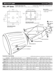
The safety factor is the ratio of the
ultimate break strength
ultimate break strength
ultimate break strength
ultimate break strengthultimate break strength
working load limit
working load limit
working load limit
working load limitworking load limit
. The ultimate break strength rep-
resents the force at which a part will structurally fail. The
working load limit is the maximum load that the user shall ap-
ply. The safety factor provides a margin of safety above the
working-load limit to accommodate normal dynamic loading
The use of mounting configurations other than recommended
by Electro-Voice in this manual are at the risk of the user.
Suspending any object is potentially dangerous and
should only be attempted by individuals who have a
thorough knowledge of the techniques and regula-
tions of suspending objects overhead. Electro-Voice
strongly recommends that loudspeakers be suspen-
ded taking into account all current national, federal,
state, and local laws and regulations. It is the re-
sponsibility of the installer to ensure all loudspeak-
ers are safely installed in accordance with all such
requirements. When loudspeakers are suspended,
Electro-Voice strongly recommends the system be in-
spected at least once per year or as laws and regula-
tions require. If any sign of weakness or damage is
detected, remedial action should be taken immedi-
ately. The user is responsible for making sure the
wall, ceiling, or structure is capable of supporting all
objects suspended overhead. Any hardware used to
suspend a loudspeaker not associated with Electro-
Voice is the responsibility of others.
Prior to use, inspect the suspension points and associated
hardware for any cracks, deformations, broken welds, corro-
sion, missing or damaged components which could reduce the
suspension points strength. Replace any damaged hardware.
Never exceed the limitations or maximum recommended load
intended for the suspension points. As an added safety meas-
ure, it is suggested the user install an extra suspension point
back to the building structural supports. This redundant safety
point should have as little slack as possible (less than one inch
is preferable). Prior to each use, inspect the loudspeaker en-
closures for any cracks, deformations, missing or damaged
components, which could reduce enclosure strength. Replace
any loudspeaker systems that are damaged or missing hard-
For information on warranty periods and after sales service,
please visit: www.electrovoice.com/warranty
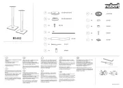
Make sure that all parts are included and not damaged. If the
packaging or any parts are damaged, contact your shipper. If
any parts are missing, contact your Sales or Customer Service
1 Bracket with through hole
1 Bracket with slotted hole
2 Screw, M6x20, Phillips, Pan Head, Steel,
1 Quick installation guide
Thank you for choosing ZLX-G2-BRKT accessory. This manual
describes how to install the mounting bracket with the ZLX-G2
full-range loudspeaker system.
The ZLX-G2-BRKT is used to mount a ZLX-12-G2, ZLX-12P-G2,
ZLX-15-G2, or ZLX-15P-G2 full-range loudspeaker to a wall,
ceiling, pole, pipe, or truss.
The mounting bracket kit contains the following:
1 Bracket with through hole
1 Bracket with slotted hole
2 Screw, M6x20, Phillips, Pan Head, Steel,
1 Quick installation guide
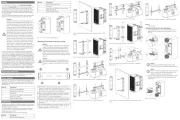
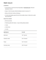
Fig.1: 12-inch and 15-inch powered version
Mounting the U-bracket to the wall or ceiling
Due to the weight of the Electro-Voice loudspeaker
system, it is imperative the bracket is properly se-
cured to the wall. The choice of fastener (not sup-
plied) will be determined by the material and con-
struction of the mounting surface. The user is re-
sponsible to ensure the mounting surface and fasten-
ers are capable of supporting the weight of the loud-
We recommend that two or more persons lift and
place heavier loudspeakers. Single person lift and
placement of heavier loudspeakers could cause in-
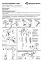
For vertical or horizontal mounting using four screws OR
pole/truss mounting for nominal pipe size up to 2" (DN50)
using two U-bolts. Accepts fastener diameters up to 3/8" or
M10. Refer to for slot dimensions.Technical data
For horizontal suspension using two threaded rods up to
5/8" or M16 diameter OR pole/truss mounting using two
Electro-Voice TCA-1 truss clamp adapters.
For pole mounting using one U-bolt for nominal pipe size
between 4" (DN100) and 6" (DN175). Accepts fastener dia-
meters up to 5/8" or M16. Refer to for slotTechnical data
For horizontal suspension using two threaded rods OR ver-
tical or horizontal mounting using two screws. Accepts
fastener diameters up to 3/8" or M10.
Fig.2: Vertical or horizontal wall mounting using four 3/8” or M10
Fig.3: Vertical pole mounting using 2” or DN50 U-Bolts
Fig.4: Horizontal pole/truss mounting using 2” or DN50 long U-Bolts
Fig.5: Horizontal suspension using 1/2” or M16 threaded rods
Fig.6: Horizontal mounting using TCA-1 truss clamps
Fig.7: Vertical mounting using TCA-1 truss clamps
Fig.8: Horizontal pole/truss mounting using 4” to 6” or DN100 to
Fig.9: Vertical or horizontal wall mounting using two 3/8” or M10
Fig.10: Horizontal suspension using 3/8” or M10 threaded rods
Attaching the bracket to the loudspeaker
1. Using a screwdriver with a hex drive, remove the four
screws that hold the top and bottom handles to the en-
Keep the eight handle mounting screws. These
screws are necessary to install the smaller brackets.
When mounting the loudspeaker in a vertical orienta-
tion, the bracket with slotted hole needs to be in-
stalled at the bottom of the loudspeaker.
2. Using the eight screws removed from the handles, install
the two smaller brackets to the top and bottom of the