Emerson 1F83H-21NP Manual
Emerson
Termostater
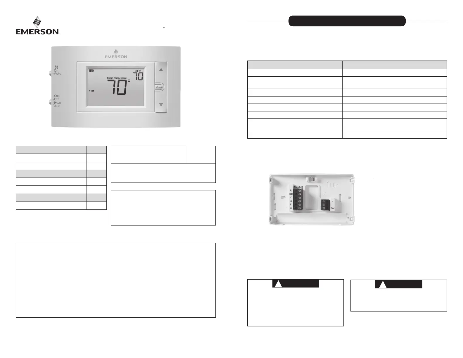
1F83H-21NP
| Mærke: | Emerson |
| Kategori: | Termostater |
| Model: | 1F83H-21NP |
Har du brug for hjælp?
Hvis du har brug for hjælp til Emerson 1F83H-21NP stil et spørgsmål nedenfor, og andre brugere vil svare dig
Termostater Emerson Manualer
14 Januar 2025
13 Januar 2025
8 Juli 2024
5 Juli 2024
Termostater Manualer
- Zehnder
- Watts
- Danfoss
- Bticino
- Tylö
- Siemens
- Bosch
- Plieger
- Remeha
- Drayton
- Seitron
- Honeywell
- SilverCrest
- Horstmann
- ICY
Nyeste Termostater Manualer
15 Januar 2025
15 Januar 2025

13 Januar 2025

12 Januar 2025

15 Oktober 2024

14 Oktober 2024

13 Oktober 2024

10 Oktober 2024

10 Oktober 2024
10 Oktober 2024