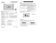
Emerson 1F85U-22PR Manual
| Mærke: | Emerson |
| Kategori: | Termostat |
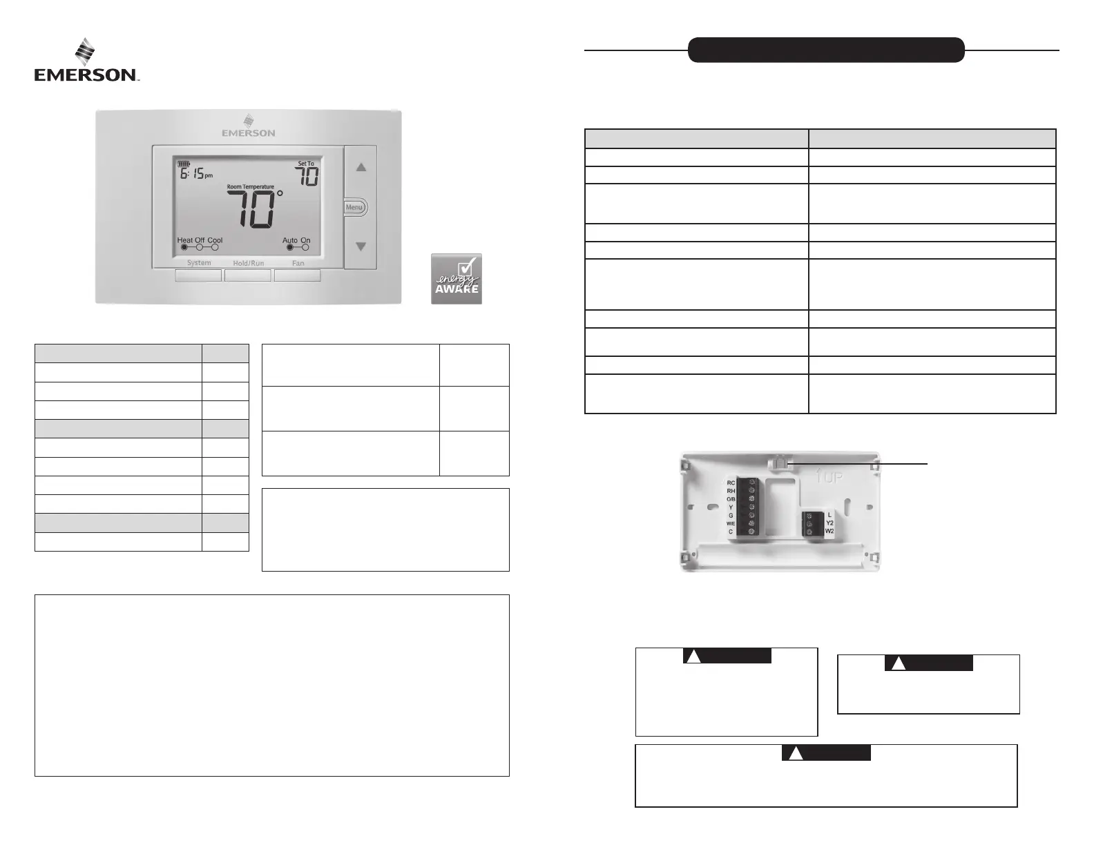
| Model: | 1F85U-22PR |
Har du brug for hjælp?
Hvis du har brug for hjælp til Emerson 1F85U-22PR stil et spørgsmål nedenfor, og andre brugere vil svare dig
Termostat Emerson Manualer
1 Oktober 2025

22 August 2024
22 August 2024
22 August 2024
22 August 2024
22 August 2024
22 August 2024
22 August 2024
Termostat Manualer
- Z-Wave
- Dnt
- RADEMACHER
- Ouellet
- Otio
- Perel
- Elektrobock
- Wachendorff
- Eneco
- GE
- SPC
- Grässlin
- Easy Timer
- Delta Dore
- Heimeier
Nyeste Termostat Manualer

2 December 2025

1 December 2025

28 November 2025

27 November 2025

27 November 2025

27 November 2025

27 November 2025

27 November 2025

27 November 2025

26 November 2025