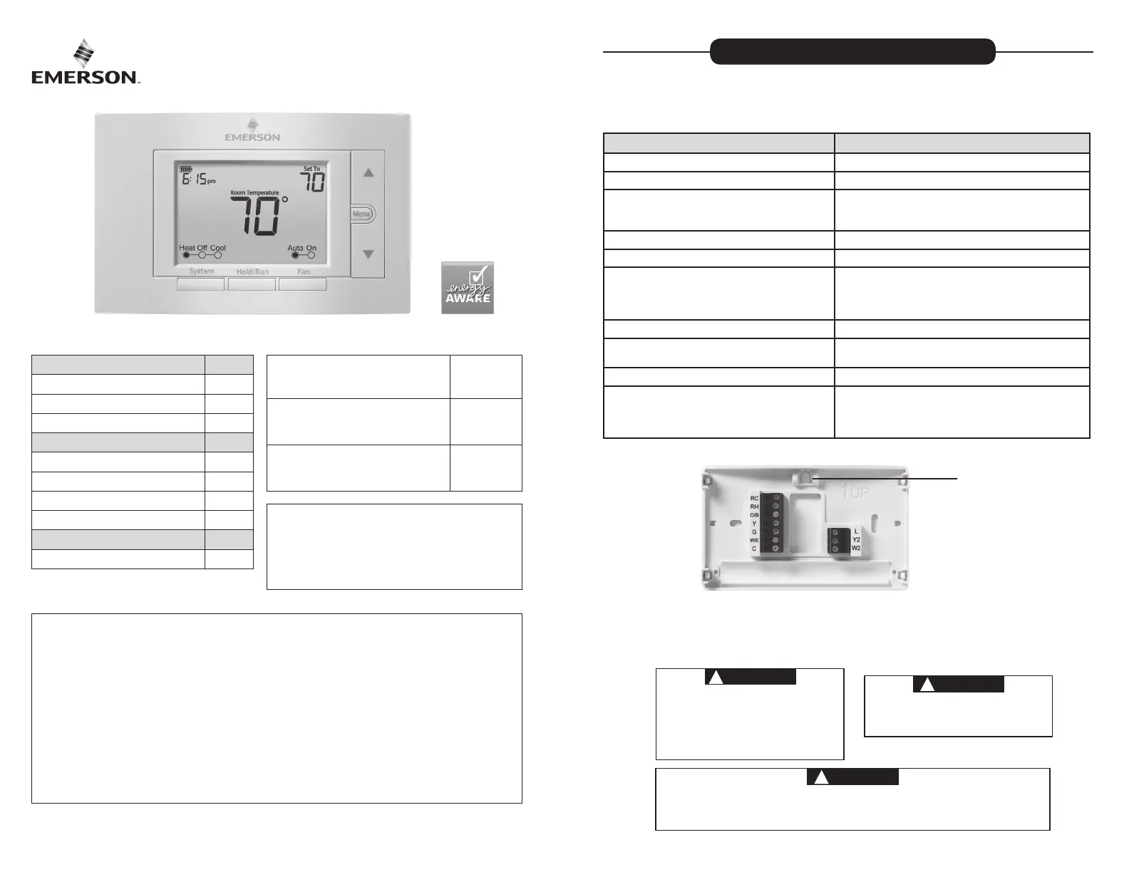
Emerson 1F85U-42PR Manual
| Mærke: | Emerson |
| Kategori: | Termostat |
| Model: | 1F85U-42PR |
Har du brug for hjælp?
Hvis du har brug for hjælp til Emerson 1F85U-42PR stil et spørgsmål nedenfor, og andre brugere vil svare dig
Termostat Emerson Manualer
1 Oktober 2025

22 August 2024
22 August 2024
22 August 2024
22 August 2024
22 August 2024

22 August 2024
22 August 2024
Termostat Manualer
- MKC
- Basetech
- Magnum
- Rose LM
- OJ ELECTRONICS
- Arnold Rak
- Carel
- RADEMACHER
- Plieger
- EQ3
- Wallair
- King
- Ferguson
- Danfoss
- Thermy
Nyeste Termostat Manualer

2 December 2025

1 December 2025

28 November 2025

27 November 2025

27 November 2025

27 November 2025

27 November 2025

27 November 2025

27 November 2025

26 November 2025