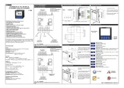
Emko CHANNEL8A-N Manual


Læs gratis den danske manual til Emko CHANNEL8A-N (4 sider) i kategorien Temperaturregulator. Denne vejledning er vurderet som hjælpsom af 32 personer og har en gennemsnitlig bedømmelse på 5.0 stjerner ud af 16.5 anmeldelser. Har du et spørgsmål om Emko CHANNEL8A-N, eller vil du spørge andre brugere om produktet?

Side 1/4
ENGCHANNEL8A-N01V0003/17
CHANNEL8A-N
8CHANNEL ANALOGSCANNER
96x96DIN1/4
12±1mm/0.47inch
84mm/3.31inch
Maksimum15 0.59inchmm/
92mm/3.62inch
92mm/3.62inch
129mm/5.08inch(min)
PanelKesiti
320x240Pixel
TFT LCD
Standart
Function
Buttons
MENU BUTTON
Used to access Menu page.
ENTER BUTTON
Used to go in to selected page, to make parameter's cell
available tochange and to confirm parameter’s change.
AUTO BUTTON
Used to auto-scan pages.
BACK BUTTON
Used to go back to previous menu and to cancel
parameter's change.
UP BUTTON
Used to go up in menus and lists and also used to increase
parameter's value.
LEFTBUTTON
Usedtogoleftinmenus.
DOWNBUTTON
Usedtogodowninmenusandlistsandalsousedto
decreaseparameter'svalue.
RIGHTBUTTON
Usedtogorightinmenus.
F4
F1
F2
F3
DELETEBUTTON
Usedtoeraselogsonthescreen.
SETTINGS
LOGS
ADVANCE
SETTINGS
LANGUAGE
CHANNEL8A-N8Channel AnalogScanner
-320x240pixelTFTLCDdisplay
-8 Analoginputs
-ON-OFFcontrol
-Relayor(pnp “source”)transistoroutput
-Sensorerrordetection
- Adjustabletemperatureoffset
-3Differentalarmandpre-alarmtypesforeachchannel
(High,LowandBand Alarms)
-Userdefinedchannellabels
-Displayscanmodes
-OperatingwithRealTimeClock(RTC)
-ModBusRTUcommunicationprotocol
(RS-232,RS-485andEthernetcommunication)
-DataLoggingtoUSBFlashMemory
- Adjustabledataloggingtimeinterval
-Passwordprotectionforprogrammingmode
CHANNEL8A-N series 8 channel analog scanner devices are designed
for measuring and logging temperature. They can be used in many
applications with their, alarm outputs, selectable alarm functions, RS-
232 / RS-485 / Ethernet / USB communications.
SPECIFICATIONS
INPUT
AnalogInputs:
Accuracy:
SamplingTime:
OUTPUT
Relay:
DISPLAY
LCDDisplay:
POWERSUPPLY
ENVIRONMENTAL RATINGS
OperatingTemperature:
Humidity:
ProtectionClass:
PHYSICAL SPECIFICATIONS
Weight:
Dimension :
Panel Cut-Out :
0-20mA /4-2mA and0-10VDC Analogue
±0.25%offullscale
400ms
ax.1A@24V
320x240
0...50°C
0-90%RH(nonecondensing)
IP65atfront,IP20atrear
0gr.
96 x 96 mm, Depth:96 mm
92 x 92 mm
W
W
40
Resolution:
InputRessistance:
Transistor:
14Bits
100 for0-20mA inputand
68k for0-10Vinput
ResistiveLoad5A@250V
(ElectricalLife:100.000operation(FullLoad)
PNP(source)typetransistoroutput(M )
pixel TFT LCD
100-240V (-%15/+%10)50/60Hz.7VA
24V (-%15/+%10)50/60Hz.7VA
24V (-%15/+%10)7W
(Itmustbedeterminedinorder.)
V
Z
V
V
Z
ElectricalWiringDiagram
DevicewithRelayOutputs
RS232
COMMUNICATION
5x5A@250V
COMMON-1
COMMON-2
16
21 22
23
24
25 26
27
28 29 30
17
18 19 20
1 2
3
4
5
6
7 8 9 10
11 12
13
14
15
CH-1 ALARM
OUTPUT
CH-
OUTPUT
2 ALARM
CH-
OUTPUT
3 ALARM
CH-
OUTPUT
4 ALARM
CH-
OUTPUT
5 ALARM
CH-
OUTPUT
6 ALARM
CH-
OUTPUT
7 ALARM
CH-
OUTPUT
8 ALARM
GENERAL ALR.
OUTPUT
GENERAL PRE-ALR.
OUTPUT
5x5A@250V
USB2.0
COMMUNICATION
ETHERNET
OR
RS485
COMMUNICATION
CH-1CH-2CH-3CH-4CH-5CH-6CH-7CH-8
100...240V-%15;+%10)50/60Hz7VA
24V(-%15;+%10)50/60Hz7VA
24V(-%15;+%10)7W
L
(+)
N
(-)
DevicewithTransistorOutputs
RS232
COMMUNICATION
1 2
3
4
5
6 7 8 9 10
11 12
13
14
15
USB2.0
COMMUNICATION
ETHERNET
OR
RS485
COMMUNICATION
100...240V(-%15;+%10)50/60Hz7VA
24V(-%15;+%10)50/60Hz7VA
24V(-%15;+%10)7W
L
(+)
N
(-)
i
RS485, Ethernet and USB communications are optional
16
21 22
23
24
25 26
27
28 29 30
17
18 19 20
CH-1 ALARM
OUTPUT
CH-
OUTPUT
2 ALARM
CH-
OUTPUT
3 ALARM
CH-
OUTPUT
4 ALARM
CH-
OUTPUT
5 ALARM
CH-
OUTPUT
6 ALARM
CH-
OUTPUT
7 ALARM
CH-
OUTPUT
8 ALARM
GENERAL ALR.
OUTPUT
GENEAL PRE- ALR.
OUTPUT
10x1A@24V
TRANSISTOROUTPUTS
POWERSUPPLY
24V±%15
i
RS485, Ethernet and USB communications are optional
RelayOutputs
(AlarmOutputsfor
Channels6to8,
General AlarmOutputand
GeneralPre-AlarmOutput)
CH=CHANNEL
PowerSupplyInput
(Itmustbedeterminedinorder.)
Common1
Common2
RelayOutputs
(AlarmOutputsfor
Channels1to5)
PowerSupplyInput
(Itmustbedeterminedinorder.)
TransistorOutputs
(AlarmOutputsfor
Channels1to8,
General AlarmOutputand
GeneralPre-AlarmOutput)
CH=CHANNEL
Maximum
CHANNEL8A-NFrontViewandDimensionsof
PanelCut-Out
1-Before mounting the device
in your panel, make sure that
the cut-out is of the right size.
2-Check front panel gasket
position
3-Insert the device through the
cut-out. If the mounting clamps
are on the unit, put out them
before inserting the unit to the
panel.
PanelMounting
InstallationFixingClamp
The unit is designed for panel
mounting.
1-Insert the unit in the panel
cut-out from the front side.
2- Insert the mounting clamps
to the holes that located top
and bottom sides of device and
screw up the fixing screws until
the unit completely immobile
within the panel.
RemovingfromthePanel
1-Loosen the screws.
2-Pull mounting clamps from
top and bottom fixing sockets.
3-Pull the unit through the
front side of the panel
DefinitionofFrontPanel
AGND
ProcessInputs
(4-20mA /0-20mA)
(0-10V)
ı
+
ı
+
ı
+
ı
+
ı
+
ı
+
ı
+
ı
+
ı
+
ı
+
0-20mA Z
0-10V Z
4-20mA Z
0-20mA Z
0-10V
Z
4-20mA Z
0-20mA Z
0-10V Z
4-20mA Z
0-20mA Z
0-10V
Z
4-20mA
Z
0-20mA Z
0
-10
V Z
4-20mA
Z
0-20mA Z
0-10V Z
4-20mA Z
0-20mA Z
0-1
0V Z
4-20mA Z
0-20mA Z
0-1
0V
Z
4-20mA Z
AGND
ProcessInputs
(4-20mA /0-20mA)
(0-10V)
ı
+
ı
+
ı
+
ı
+
ı
+
ı
+
ı
+
ı
+
ı
+
ı
+
0-20mA Z
0-10V Z
4-20mA Z
0-20mA Z
0-10V
Z
4-20mA Z
0-20mA Z
0-10
V Z
4
-20mA Z
0-20mA
Z
0-10V
Z
4-20mA Z
0-20mA Z
0
-
10
V Z
4-20mA
Z
0
-20mA Z
0
-10V
Z
4-20mA Z
0-20mA Z
0-10V Z
4
-20mA Z
0-20mA Z
0-10V Z
4-20mA Z
CH-1CH-2CH-3CH-4CH-5CH-6CH-7CH-8
96mm/3.78inch
96mm/3.78inch
F1 F2 F3 F4
A
1
2
3
F1
F2
F3
F4
A
1
2
F1
F2
F3
F4
A
F4F1
F2
F3
F4
F1
F2
F3
A
3
1
2
F1
F2
F3
F4
A


Produkt Specifikationer

Mærke: Emko
Kategori: Temperaturregulator
Model: CHANNEL8A-N

Har du brug for hjælp?

Hvis du har brug for hjælp til Emko CHANNEL8A-N stil et spørgsmål nedenfor, og andre brugere vil svare dig


Temperaturregulator Emko Manualer
Emko

Emko ESM-9420 Manual

7 September 2025
Emko

Emko ESM-1520-N Manual

30 August 2024
Emko

Emko ECO PID+ Manual

30 August 2024
Emko

Emko Eco PID Manual

30 August 2024
Emko

Emko Eco Lite Manual

30 August 2024
Emko

Emko CHANNEL8A-N Manual

28 August 2024
Emko

Emko ESM-7720 Manual

28 August 2024
Emko

Emko ESM-3711-CN Manual

28 August 2024
Emko

Emko ESM-4410 Manual

27 August 2024
Emko

Emko ESM-4435 Manual

27 August 2024

Temperaturregulator Manualer

Nyeste Temperaturregulator Manualer

Inkbird

Inkbird ITC-308-WIFI Manual

30 September 2025
Inkbird

Inkbird ITC-306T-WIFI Manual

29 September 2025
Gossen Metrawatt

Gossen Metrawatt R6000 Manual

26 September 2025
SRS

SRS PTC10 Manual

3 September 2025
Fluke

Fluke 1504 Manual

2 September 2025
Daikin

Daikin KRCS01-8B Manual

11 August 2025
Daikin

Daikin BRC4C61 Manual

11 August 2025
IFM

IFM LT8922 Manual

9 August 2025