Emko EPM-3790 Manual
Emko
Ikke kategoriseret
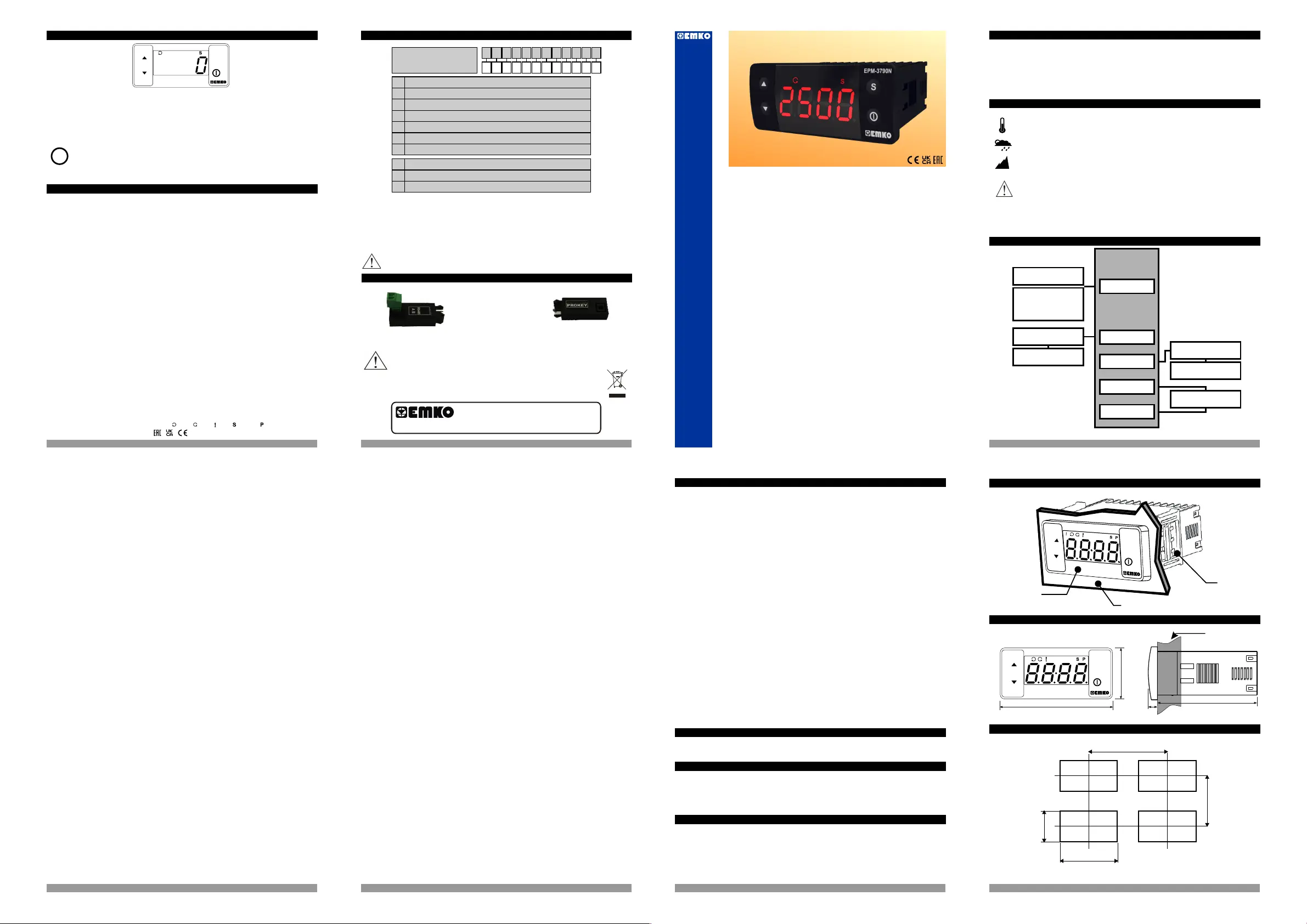
EPM-3790
| Mærke: | Emko |
| Kategori: | Ikke kategoriseret |
| Model: | EPM-3790 |
Har du brug for hjælp?
Hvis du har brug for hjælp til Emko EPM-3790 stil et spørgsmål nedenfor, og andre brugere vil svare dig
Ikke kategoriseret Emko Manualer
8 September 2025
8 September 2025
8 September 2025
8 September 2025
8 September 2025
8 September 2025
8 September 2025
8 September 2025
8 September 2025
7 September 2025
Ikke kategoriseret Manualer
- Techni Mobili
- Twisted Electrons
- Gridbyt
- Maclean
- ECTIVE
- Heissner
- Ferroli
- Brizo
- Telestar
- Taga Harmony
- Fagor
- AFK
- ZCover
- Platypus
- SureFlap
Nyeste Ikke kategoriseret Manualer
5 November 2025
5 November 2025

5 November 2025
5 November 2025
5 November 2025
5 November 2025
5 November 2025
5 November 2025
5 November 2025

5 November 2025