2
1.Preface
1.2 GeneralSpecifications
ESM-3712-HC
Optional
Standard
NTC
PTC
JorKTypeTC
2-wirePT100
2-wirePT1000
Output-1 (RelayOut)
HeatingorCooling
Function
ON/OFFOperation
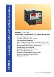
ESM-3712-HC series temperature controllers are designed for measuring and controlling
temperature. They can be used in many applications with their On / Off control form, heating and
cooling control form and easy-use properties. Some application fields which they are used are
below:
Glass Heating
Food BakingOvens
Plastic Incubators
Petro-Chemistry Storages
Textile, Automative AirConditioning
MachineProductionIndustries Etc...
Etc...
Application Fields Applications
TemperatureSensor
Input
PowerSupply
Input
OperatingTemperature:
Max.OperatingHumidity :
Altitude :
0to50°C
90%Rh(non-condensing)
Upto2000m.
Forbidden Conditions:
Corrosive atmosphere, Explosive atmosphere,
Home applications (The unit is only for industrial applications)
1.1 OperatingConditions
c
3
4
13
14
16
15
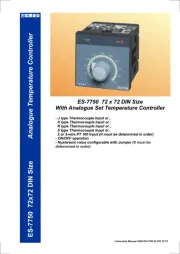
ESM-3712-HC77x35DINSizeTemperatureController
-3Digitsdisplay
-PTCinputor
NTCinputor
JTypeThermocoupleinputor
KTypeThermocoupleinputor
2-wirePT-100inputor
2-wirePT-1000input(Itmustbedeterminedinorder)
-Temperaturecontroloutputandalarmoutput
-Processandalarmsetvaluesboundaries
-Selectableheatingorcoolingfunction
- Adjustabletemperatureoffsetvalue
-RelayorSSRdriveroutput
-Operationselectionofcompressoroperatescontinuously,stops
oroperatesperiodicallyincaseofprobedefect
-Compressorprotectiontimes
-Passwordprotectionforprogrammingsection
ESM-3712-HC(SET+ ALARM)
77x35DINSize
Digital,ON/OFFTemperatureController
InstructionManual.ENGESM-3712-HC01V0403/14
Standard
OptionalSupplyInput
24V ( )
50/60Hz
W -%15;+%10
100-240V (-%15;+ )
50/60Hz
V %10
ControlOutput
Output-2(RelayOut)
AlarmOutput
Output-1(SSROut)
ControlOutput
Output-2(SSROut)
AlarmOutput
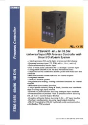
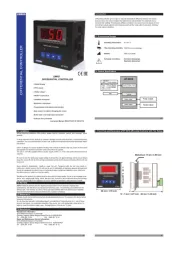
2.1FrontViewandDimensionsofESM-3712-HCTemperatureController
77mm/3.03inch
35mm/1.38inch
2.2PanelCut-Out
110mm/4.33inch(min)
50mm/1.97inch(min)
29mm/1.14inch
71mm/2.79inch
Maximum15 0.59inchmm/
58.5mm/2.30inch
4mm/0.16inch
2.GeneralDescription
MountingClamp
FrontPanel
IP65protection
NEMA 4X
Panelsurface
(maximumthickness15mm/0.59inch)
TemperatureController
ESM-3712-HC
SET
°C
SV
P
1.4Warranty
EMKO Elektronik warrants that the equipment delivered is free from defects in material and
workmanship. This warranty is provided for a period of two years. The warranty period starts from
the delivery date. This warranty is in force if duty and responsibilities which are determined in
warranty document and instruction manual performs by the customer completely.
1.5Maintenance
Repairs should only be performed by trained and specialized personnel. Cut power to the device
before accessing internal parts.
Do not clean the case with hydrocarbon-based solvents (Petrol, Trichlorethylene etc.). Use of
these solvents can reduce the mechanical reliability of the device. Use a cloth dampened in ethyl
alcohol or water to clean the external plastic case.
In package ,
- One piece unit
- Two pieces mounting clamps
- One piece instruction manual
A visual inspection of this product for possible damage occured during shipment is
recommended before installation. It is your responsibility to ensure that qualified
mechanical and electrical technicians install this product.
If there is danger of serious accident resulting from a failure or defect in this unit, power
off the system and the electrical connection of the device from the system.
The unit is normally supplied without a power supply switch or a fuse. Use power switch
and fuse as required.
Be sure to use the rated power supply voltage to protect the unit against damage and to
prevent failure.
Keep the power off until all of the wiring is completed so that electric shock and trouble
with the unit can be prevented.
Never attempt to disassemble, modify or repair this unit. Tampering with the unit may
results in malfunction, electric shock or fire.
Do not use the unit in combustible or explosive gaseous atmospheres.
During the equipment is putted in hole on the metal panel while mechanical installation
some metal burrs can cause injury on hands, you must be careful.
Montage of the product on a system must be done with it’s fixing clamps. Do not do the
montage of the device with inappropriate fixing clamp. Be sure that device will not fall
while doing the montage.
It is your responsibility if this equipment is used in a manner not specified in this
instruction manual.
separate
Before beginning installation of this product, please read the instruction
manual and warnings below carefully.
1.3Installation
c
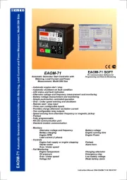
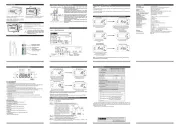
4.5EnteringToTheProgrammingMode,ChangingandSavingParameter
i
If no operation is performed in Programming mode for 20 seconds, device turns to
main operation screen automatically
ProgrammingScreen
SET
°C
SV
P
SET
°C
SV
P
SET
°C
SV
P
SET
°C
SV
P
SET
°C
SV
P
SET
°C
SV
P
SET
°C
SV
P
SET
°C
SV
P
WhenSET buttonispressed
for5seconds,“P”ledstartsto
blink.Ifprogrammingmode
enteringpasswordisdifferent
from0,programmingmode
enteringscreenwillbe
observed.
Note-1: Ifprogramming
modeaccessing
passwordis0,
hysteresisscreen
isobservedinsteadof
programmingscreen
accessingpassword
ProgrammingMode
EnteringScreen
Pressincrement
buttonforaccessing
tothepassword
PasswordEntering
PasswordEntering
Enterprogrammingmodeaccessing
passwordwithincrementanddecrement
PressSET/OKbuttonfor
accessingtotheparameters
Note-2: Parameters can be observed by pressing SET/OK button in password entering
screen without entering the programming mode entering password. But parameters can
not be changed.
HysteresisParameter
Changetheparameterwith
incrementanddecrementbuttons
HysteresisParameterValue
Parameterisaccessedbypressing
incrementbutton.Ifsetbuttonispressed,
nextparameterisshown.
HysteresisParameterValue
PressSetbuttonforsaving
theparametervalue
HysteresisParameter
PressSetbuttonforaccessing
tothenextparameter
MainOperationScreen
5secs
ProgrammingScreen
SET
°C
SV
P
SET
°C
SV
P
ProgrammingScreen
Parameterisaccessedbypressing
incrementbutton.Ifsetbuttonis
pressed,nextparameterisshown.
MinimumSetValue
Parameter
MinimumSetValue
i
If no operation is performed in Programming mode for 20 seconds, device turns to
main operation screen automatically
Changetheparameterwith
incrementanddecrement
SET
°C
SV
P
SET
°C
SV
P
i
Other Programming mode parameters can be
accessed with the same method explained above,
observed and changed.
MinimumSetValue
MinimumSetValueParameteri
Changetheparameterwith
incrementanddecrement
buttons
PressSetbuttonforsavingthe
parametervalue
ProgrammingScreen
7.Specifications
DeviceType
Housing&Mounting
ProtectionClass
Weight
EnvironmentalRatings
Storage/OperatingTemperature
Storage/OperatingHumidity
Installation
OvervoltageCategory
PollutionDegree
OperatingConditions
SupplyVoltageandPower
TemperatureSensorInputs
NTCInputType
PTCInputType
ThermocoupleInputTypes
ThermoresistanceInputType
Accuracy
ColdJunctionCompensation
SensorBreakProtection
SamplingCycle
ControlForm
RelayOutput
OptionalSSROutput
Display
Leds
Approvals
: TemperatureController
:77mmx35mmx62.5mmplastichousingforpanel
Mounting.Panelcut-outis71x29mm.
:NEMA 4X(IP65atfront,IP20atrear).
: Approximately0.20Kg.
: Standard,indooratanaltitudeoflessthan2000meters
withnonecondensinghumidity.
:-40 Cto+85 C/0 Cto+50 C
:90%max.(Nonecondensing)
:Fixedinstallation
:II.
: II,officeorworkplace,noneconductivepollution
: Continuous
: 50/60Hz.2
24V 50/60Hz.2
:NTC,PTC, TC,RTD
:NTC(10k @.25°C)
:PTC(1000 @.25°C)
:J,K(IEC584.1)(ITS90)
:PT-100,PT-1000(IEC751)(ITS90)
:±1%offullscaleforthermocoupleandthermoresistance
: Automatically±0.1°C/1°C.
:Upscale
:3samplespersecond
:ON/OFF
:ResistiveLoad10 A@250V
(ElectricalLife:100.000operation(FullLoad)
:Maximum24mA,Maximum16V
:14mmRed3digitsLEDDisplay
:SV(Green),OUT (Red),P(Red), Alarm(Red)3mm
:GOST-R,
o o o o
VA
VAV
V
Z
W
W
100-240V (-%15;+%10)
(-%15;+%10)
24V (-%15;+%10)2W
V
Z
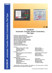
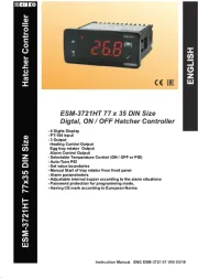
5.FailureMessagesinESM-3712-HCTemperatureController
Probe defect in analogue inputs. Sensor
connection is wrong or there is no sensor
connection.
TemperatureController
ESM-3712-HC
SET
°C
SV
P
6.OrderingInformation
All order information of ESM-3712-HC
Temperature Controller are given on the
table at left. User may form appropriate
device configuration from information and
codes that at the table and convert it to the
ordering codes.
Firstly, supply voltage then other
specifications must be determined. Please
fill the order code blanks according to your
needs.
Please contact us, if your needs are
out of the standards.
V
Z
Symbol means Vac,
Symbol means Vdc,
Symbol means Vac/dcW
c
A BC D E FG HI /
/
U
V W Z/
/
0 00 1 0 0
SupplyVoltageA
12
05
09
J,FeCuNiIEC584.1(ITS90)
PTC(Note-1)
InputType
BC
Scale(°C)
-50°C
150°C
0°C 800°C
-19.9°C 99.9°C
PT 100,IEC751(ITS90)
ESM-3712-HC(77x35DINSize)
100...240V (-%15;+%10)50/60HzV
1
24V (-%15;+%10)50/60Hz 24V (-%15;+%10)V Z
2
Customer
9
10
K,NiCrNiIEC584.1(ITS90)
-50°C 400°C
0°C 999°C
11
PT 100,IEC751(ITS90)
OrderingInformation
13
-19.9°C 99.9°C
PT 1000,IEC751(ITS90)
-50°C 400°C
14
PT 1000,IEC751(ITS90)
-19.9°C 99.9°C
15
PTC(Note-1)
18
NTC(Note-1)
-50°C
100°C
-19.9°C 99.9°C
19
NTC(Note-1)
1
E
01
FG
ProcessOut
AlarmOut
2
02
Outputs
ProcessOut
AlarmOut
SSRDriverOutput(Max.24mA,16V )Z
SSRDriverOutput(Max.24mA,16V )Z
RelayOutput(10 @250V atresistiveload,1NO)A V
RelayOutput(5 @250V atresistiveload,1NO)A V
Temp.SensorwhichisgivenwithESM3712HC
V
0
None
1
PTC-M6L40.K1.5 (PTC AirProbewith1.5msiliconcable)
2
PTCS-M6L30.K1.5.1/8” (PTCLiquidProbewith1.5msilicon
cable)
Customer
3
NTC-M5L20.K1.5 (NTCProbe,thermoplasticmouldedwith
1.5mcableforcoolingapplication)
4
NTC-M6L50.K1.5
(NTCProbe,stainlesssteelhousingwith
1.5mcableforcoolingapplication)
9
Note-1:IfinputtypeisselectedPTCorNTC(BC=12,15,18,19),
Temperaturesensorisgivenwiththedevice.Forthisreason,
IfinputtypeisselectedasPTC,sensortype(V=0,1or2)or
IfinputtypeisselectedasNTC,sensortype(V=0,3or4)mustbe
declaredinorderinginformation.
ManufacturerInformation:
Repairandmaintenanceserviceinformation:
EmkoElektronikSanayive Ticaret A.Þ.
DemirtaþOrganizeSanayiBölgesiKaranfilSk.No:616369BURSA / TURKEY
Tel:+902242611900
Fax:+902242611912
EmkoElektronikSanayive Ticaret A.Þ.
DemirtaþOrganizeSanayiBölgesiKaranfilSk.No:616369BURSA / TURKEY
Tel:+902242611900
Fax:+902242611912
8.OtherInformations
YourTechnologyPartner
www.emkoelektronik.com.tr
Thankyouverymuchforyourpreferenceto
useEmkoElektronikproducts,pleasevisitour
webpagetodownloadusermanual.