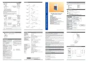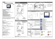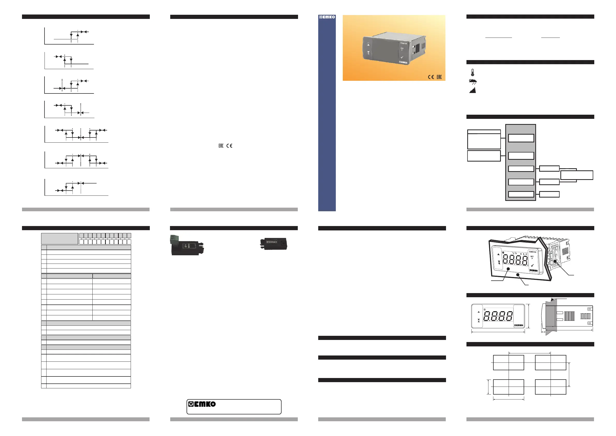
2.2 Panel Cut-Out
2. General Description
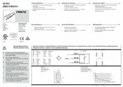
2.1 Front View and Dimensions of ESM-3720Temperature Controller
Mounting Clamp
Panel Surface
(maximum thickness 15 mm / 0.59 inch)
Front Panel
IP65 protection
NEMA 4X
ESM-3720 77x35 DIN Size Temperature Controller
Instruction Manual. ENG ESM-3720 01 V03 11/17
- 4 Digits Display
- NTC Input or
PTC Input or
(Must be determined in order.)
- Adjustable temperature offset
- PID or
- Operation selection of compressor operates continuously,
stops or operates periodically in case of sensor defect
- Compressor protection delays
- Alarm parameters
- Adjustable internal buzzer according to sensor defect status.
- Password protection for programming section
- Installing parameters using Prokey
- Remote access, data collecting and controlling with Modbus RTU
- Having CE mark according to European Norms
J Type thermocouple Input or,
K Type thermocouple Input or,
2-Wire PT-100 Input or,
2-Wire PT-1000 Input
ON/OFF temperature control
- Selectable heating or cooling function
- Selection of operation with hysteresis
- Adjustable temperature offset
- Set value low limit and set value high limit boundaries
ESM-3720 77 x 35 DIN Size
Digital Temperature Controller
Operating Temperature : -20 to 70 °C
Max. Operating Humidity : 90% Rh (non-condensing)
Altitude : Up to 2000 m.
Forbidden Conditions:
Corrosive atmosphere
Explosive atmosphere
Home applications (The unit is only for industrial applications)
c
1.2 General Specifications
1.Preface
ESM-3720 series temperature controllers are designed for measuring and controlling
temperature. They can be used in many applications with their On / Off control form, heating
and cooling control form and easy-use properties. Some application fields which they are
used are below:
Application Fields Applications
Glass Heating
Food Baking Ovens
Plastic Incubators
Petro-Chemistry Storages
Textile, Automative Air Conditioning
Machine Production Industries Etc... Etc...
2
1.1 Environmental Ratings
3 41615
13 14
A visual inspection of this product for possible damage occurred during shipment is
recommended before installation. It is your responsibility to ensure that qualified mechanical
and electrical technicians install this product.
If there is danger of serious accident resulting from a failure or defect in this unit, power off the
system and separate the electrical connection of the device from the system.
The unit is normally supplied without a power supply switch or a fuse. Use power switch and fuse
as required.
Be sure to use the rated power supply voltage to protect the unit against damage and to prevent
failure.
Keep the power off until all of the wiring is completed so that electric shock and trouble with the
unit can be prevented.
Never attempt to disassemble, modify or repair this unit. Tampering with the unit may results in
malfunction, electric shock or fire.
Do not use the unit in combustible or explosive gaseous atmospheres.
During putting equipment in hole on the metal panel while mechanical installation some metal
burrs can cause injury on hands, you must be careful.
Montage of the product on a system must be done with it’s fixing clamps. Do not do the montage
of the device with inappropriate fixing clamp. Be sure that device will not fall while doing the
montage.
It is your responsibility if this equipment is used in a manner not specified in this instruction
manual.
EMKO Elektronik warrants that the equipment delivered is free from defects in material and
workmanship. This warranty is provided for a period of two years. The warranty period starts
from the delivery date. This warranty is in force if duty and responsibilities which are determined
in warranty document and instruction manual performs by the customer completely.
Repairs should only be performed by trained and specialized personnel. Cut power to the
device before accessing internal parts.
Do not clean the case with hydrocarbon-based solvents (Petrol, Trichlorethylene etc.). Use of
these solvents can reduce the mechanical reliability of the device. Use a cloth dampened in
ethyl alcohol or water to clean the external plastic case.
1.3 Installation
1.4 Warranty
1.5 Maintenance
1.6 Manufacturer Company
Manufacturer Information:
Emko Elektronik Sanayi ve Ticaret A.Ş.
Demirtaş Organize Sanayi Bölgesi Karanfil Sk. No:6 16369 BURSA/TURKEY
Phone : +90 224 261 1900
Fax : +90 224 261 1912
Repair and maintenance service information:
Emko Elektronik Sanayi ve Ticaret A.Ş.
Demirtaş Organize Sanayi Bölgesi Karanfil Sk. No:6 16369 BURSA /TURKEY
Phone : +90 224 261 1900
Fax : +90 224 261 1912
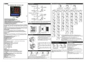
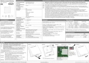
6.5 Alarm Types
All order information of ESM-3720 Temperature Controller are given on the table at above. User may
form appropriate device configuration from information and codes that at the table and convert it to the
ordering codes.Firstly, supply voltage then other specifications must be determined. Please fill the order
code blanks according to your needs.
Please contact us, if your needs are out of the standards.
8.Ordering Information
Note-1:If input type is selected PTC or NTC (BC= 12, 18), Temperature sensor is given with the
device.For this reason, if input type is selected as PTC,sensor type (V = 0,1 or 2) or if input type is
selected as NTC, sensor type (V = 0,3 or 4) must be declared in ordering information.
ESM-3720
V Þ Vac,
Z Þ Vdc
Þ Vdc or Vac can be appliedW
c
Power Supply
Input
Temperature Sensor
Input
76 mm / 3 inch
O
F
O
C
S
P
6 mm / 0.24 inch
34,5 mm / 1.36 inch
65 mm / 2.56 inch
Maximum 15 mm / 0.59 inch
110 mm / 4.33 inch (min)
71 mm / 2.79 inch
29 mm / 1.14 inch
50 mm / 1.97 inch (min)
230V ( %15) 50/60HzV ±
Optional Supply Voltage
- 30 V Z
115 V (±%15) 50/60Hz,
24 V (±%15) 50/60Hz,
24 V (±%15) 50/60Hz,
10
V
V
W
Standard
A BC D E FG HI /
/
U
V W Z/
/
0 1 0 0
1
Relay Output (16(8) A@250 V V,at resistive Load, 1 NO )
Control Output
E
Supply VoltageA
Input Type
BC
Scale(°C)
ESM-3720
4
-50°C/-58°F ; 150°C/302°F
12
PTC (Not-1)
Temp. Sensor which is given with ESM-3720
V
0
None
3
NTC-M5L20.K1.5 (NTC Sensor, thermoplastic moulded with 1.5 m cable
for cooling application)
4
NTC-M6L50.K1.5 (NTC Sensor, stainless steel housing with 1.5 m cable
for cooling application)
9
Customer
115V ( %15) 50/60Hz - 1.5VAV ±
5
230V ( %15) 50/60Hz - 1.5VAV ±
01 00
8
10 - 30 V Z
-50°C/-58°F ; 100°C/212°F
18
NTC (Not-1)
1
PTC-M6L40.K1.5 (PTC Air Probe 1.5 mt Silicon Cable)
2
PTCS-M6L30.K1.5.1/8” (PTC Liquid Probe 1.5 mt Silicon Cable)
(77x35 DIN Sizes)
Your Technology Partner
www.emkoelektronik.com.tr
Thank you very much for your preference to
use Emko Elektronik products, please visit our
web page to download detailed user manual.
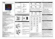
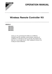
9.Optional Accessories
RS-485 Communication
Interface
1.RS-485 Module 2.PROKEY Programming Module
The device is programmed(Upload or
Download) by using The parameters.
ü
ESM3720
SET
P
0°C/32°F ; 800°C/1472°F
05
J ,Fe CuNi IEC584.1(ITS90)
0°C/32°F ; 999°C/1830°F
10
K ,NiCr Ni IEC584.1(ITS90)
-50°C/-58°F ; 400°C/752°F
11
PT 100, IEC751(ITS90)
-19.9°C/-4°F ; 99.9°C/212°F
09
PT 100, IEC751(ITS90
-50°C/-58°F ; 400°C/752°F
14
PT 1000, IEC751(ITS90)
-19.9°C/-4°F ; 99.9°C/212°F
13
PT 1000, IEC751(ITS90
3
24V ( %15) 50/60Hz - 1.5VAV ±
NTC, PTC,
J or K Type TC
2-Wire PT-100
2-Wire PT-1000
Output-1
Output-1
Standard
Optional
(Relay Output)
(SSR Drive Output)
2
SSR Driver Output (Maximum 20m, Maximum 17VZ )
2
24VW ( %15) 50/60Hz - 1.5VA ±
01
Relay Output (5 A@250 V V,at resistive Load, 1 NO )
Alarm Output
FG
Control Output
Control Output
Heating or Cooling
Function
PID or ON/OFF Operation
Alarm Output
Output-2
(Relay Output)
Device Type : Temperature Controller
Housing & Mounting : 76mm x 34.5mm x 71mm plastic housing for panel
Mounting. Panel cut-out is 71x29mm.
Protection Class : NEMA 4X (Ip65 at front, Ip20 at rear).
Weight : Approximately 0.20 Kg.
Environmental Ratings : Standard, indoor at an altitude of less than 2000 meters
with none condensing humidity.
o o o o
Storage / Operating Temperature : -30 C to +80 C / -20 C to +70 C
Storage / Operating Humidity : 90 % max. (None condensing)
Installation : Fixed installation
Overvoltage Category : II.
Pollution Degree : II, office or workplace, none conductive pollution
Operating Conditions : Continuous
Supply Voltage and Power :
: 115
: 24
: 24
:10 - 30
Temperature Sensor Input : NTC, PTC, TC, RTD
NTC input type : NTC (10 kW @25 °C )
PTC input type : PTC (1000 W @25 °C )
Thermocouple input type : J, K (IEC584.1) (ITS 90)
Thermoresistance input type : PT-100, PT-1000 (IEC751) (ITS 90)
Accuracy : ± 1 % of full scale for thermoresistance
Cold Junction Compensation : Automatically ± 0.1°C / ± 1°C
Sensor Break Protection : Upscale
Sampling Cycle : 3 samples per second
Control Form : PID or ON / OFF
Relay Output : 16(8) A@250 V V for Resistive load ( Output)
(Electrical life : 100.000 switching at full load)
: 5 A@250 V V for Resistive load (Alarm Output)
Optional SSR Drive Output : Maximum 20mA, Maximum V
Display : 14 mm Red 4 digits LED Display
o o
LED : S (Green), P (Green), C (Yellow), F(Yellow),
Compressor Output (Red), Heating Output (Red)
Internal Buzzer : ³83dB
Approvals :
230V ( %15) 50/60Hz - 1.5VA
V ( %15) 50/60Hz - 1.5VA
V ( %15) 50/60Hz - 1.5VA
V ( %15) 50/60Hz - 1.5VA
VZ 1.5W
15 Z
V ±
V ±
V ±
W ±
Compressor
7. Specifications
,
Process High
Alarm
Alarm
Output
Process Low
Alarm
Deviation High
Alarm
Deviation Low
Alarm
Deviation Band
Alarm
Deviation Range
Alarm
ON
OFF
Alarm
Output
Process Value
ON
OFF
Alarm
Output
Process Value
ON
OFF
Alarm
Output
Process Value
( + )
ON
OFF
Process Value
ON
OFF
Alarm
Output
Process Value
ON
OFF
Alarm
Output
Process Value
ON
OFF
Alarm
Output
Process Value
Deviation Range
High Alarm
Process
Set
Alarm
Hysteresis
Alarm
Set
Alarm
Set
Alarm
Hysteresis
Process
Set
Alarm
Set
Alarm
Hysteresis
( - )
Process
Set
Alarm
Set
Process
Set
Alarm
Hysteresis
( - )
Process
Set
Alarm
Set
( + )
Process
Set
Alarm
Set
Alarm
Hysteresis
Alarm
Hysteresis
Process
Set
( - )
Process
Set
Alarm
Set
( + )
Process
Set
Alarm
Set
Alarm
Hysteresis
Alarm
Hysteresis
Process
Set
( - )
Process
Set
Alarm
Set
Alarm
Hysteresis
A