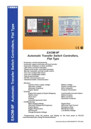
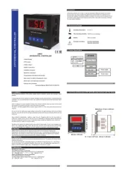
5. Changing and Saving Temperature Set Value
6.1 Defrost Zamanı Set Değerinin Değiştirilmesi ve Kaydedilmesi
Main Operation Screen
When Increment or Decrement button
pressed SET expression is shown on
display, after relasing the pressed
button ‘’S’’ led will be active and
temperature set value will be displayed.
SET Value Screen
Temperature set value can
be changed with increment
and decrement buttons.
When Compressor button pressed
temperature set value can be saved.
‘’S’’ will be inactive and goes back to
main operation screen.
Main Operation Screen
Temperature set value parameter (Default=18)
Temperature set value
°C.
, can be programmed between temperature set minimum parameter
Value and maximum temperature set value 50
230 VV ± 15%
50/60Hz - 1.5VA
3.2 Device Label and Connection Diagram
3.1 Supply Voltage Input Connection of the Device
Make sure that the power supply voltage is the same
indicated on the instrument.
Switch on the power supply only after that all the electrical
connections have been completed.
Supply voltage range must be determined in order. While
installing the unit, supply voltage range must be controlled
and appropriate supply voltage must be applied to the unit.
c
There is no power supply switch on the device. So a power
supply switch must be added to the supply voltage input.
Power switch must be two poled for seperating phase and
neutral, On/Off condition of power supply switch is very
important in electrical connection.
External fuse that on Vpower supply inputs must be on
phase connection.
External fuse that on Zpower supply inputs must be on (+)
connection.
c
10-30VZ CONNECTION DIAGRAM
4.Front Panel Definition and Accessing to the Menus
BUTTON DEFINITIONS
1. Increment Button :
** It is used to increase the value in the Set screen and Programming mode.
** In main operation screen; if this button pressed SET
2. Decrement Button :
** It is used to decrease the value in the Set screen and Programming mode.
** In main operation screen; if this button pressed SET
3. Compressor Button:
** in the Set screen and Programming mode, it is used to saving parameter.
** In main operation screen, it is used to activated compressor output.
4. Fan Button:
** In main operation screen; if this button pressed Fan outputs are can be activated with
sequentialy.
** It is used to exit from Set screen and Programming mode to main operation screen without
Saving parameter.
LED DEFINITIONS
5. Compressor Failure led :
** It is active when compressor failure statuses.
6. Compressor output led :
** This led indicates that compressor output is active
7.Fan II led :
**This led indicates that 2. Fan output is active
8.Fan I led :
**This led indicates that 1. Fan output is active
9.Fan 0 led :
** This led indicates that all fan outputs are passive.
10.Set led :
** Indicates that device is in Set value changing mode.
11.Program led :
**Blinks in programming mode .
is shown on the display, after releasing
the pressed button set value is shown on the display and SV led becomes active.
is shown on the display, after releasing
the pressed button set value is shown on the display and SV led becomes active.
5
8
10
9
5 6 9 10
121187
3
c
2.4 Removing from the Panel
1
3
5.1 Programming Mode Parameter List
Hysteresis Parameter for Compressor Output ( Default = 1 )
This parameter can be adjusted between 0 and %50 of device scale.
In ON/OFF control algorithm, temperature
value is tried to keep equal to set value by
opening or closing the last control element.
ON/OFF controlled system, temperature
value oscillates continuously. Temperature
value’s oscillation period or amplitude around
set value changes according to controlled
system. For reducing oscillation period of
temperature value, a threshold zone is formed
below or around set value and this zone is
named hysteresis.
ON
OFF
Temperature
Control
Output
Set
HSt
Time
HSt
Time
Compressor Stop-Start Delay Parameter (Default =0)
When compressor is inactive, this time delay must be expired for activation of the
compressor. It can be adjusted from 0 to 99 seconds.
Decimal Seperator Enabling Parameter ( Default = 0 )
Disable
Enable
c
a
Note-1
5
6
-
+
2
1
2
10...30 V Z 2W
When Increment or Decrement
button is pressed for 5 seconds,
“P” led starts to blink.
Main Operation
Press increment button for accessing
to the next parameter, press
decrement button for accessing to
the previous parameter.
5.3 Entering To The Programming Mode, Changing and Saving Parameter
1. Blinking expression on display. Sensor failure. Wrong sensor connection or sensor
break.
5.2 Failure Message on ESM-3770N Device
3. Electrical Wiring Diagram
5
6
7
8
9
Comp.OK
a
2x5A@250V V
16(8)A
@250V 1HPV
2
3
41
CO P.
M
AF
N
1
F
A
N
2
L
N
+
16A T Sigorta
21 3 54 6 7 8 9
P/N : ESM-3770-N
aa
Compressor OK
10 Z...30 V
10...30 V Z 2W
Programming Screen
Press compressor button for accessing to
the parameter value. Press increment button
for accessing to the next parameter, press
decrement button for accessing to the
previous parameter.
Change the value with
increment and decrement
buttons.
Decimal Seperator
Enabling Parameter
Press compressor button for
saving the parameter.
Decimal Seperator
Enabling Parameter
Decimal Seperator
Enabling Parameter
Hysteresis Parameter
2. If temperature value is over the scale high limit, temperature value and displayed on
screen with sequentialy.
6
7
Device Type : Cooling Controller
Housing&Mounting : 76mm x 34.5mm x 71mm plastic housing for panel
Mounting. Panel cut-out is 71x29mm.
Protection Against
Mechanical Impacts : 1Joule (IK06)
Protection Class : Ip65 at front, Ip20 at rear
Weight : Approximately 0.20 Kg.
Environmental Ratings : Standard, indoor at an altitude of less than 2000 meters
with none condensing humidity.
o o o o
Storage / Operating Temperature : -40 C to +80 C / -30 C to +80 C
Storage / Operating Humidity : 90 % max. (None condensing)
Installation : Fixed installation
Overvoltage Category : II.
Pollution Degree : II, office or workplace, none conductive pollution
Operating Conditions : Continuous
Supply Voltage and Power : 10...30
Temperature Sensor Input : NTC ,PTC
NTC Input type : NTC (10 kW @25 °C )
PTC Input type : PTC (1000 W @25 °C )
Accuracy : ± 1 % of full scale for thermoresistance
Sensor Break Protection : Upscale
Sampling Cycle : 3 samples per second
Control Form : ON / OFF
Relay Outputs : 16(8) A@250 V V for Resistive load(Compressor output)
(Electrical life : 100.000 switching at full load)
5 A@250 V V for Resistive load (Fan outputs)
Display : 14 mm Red 4 digit LED Display
LEDs : S (Green), P (Green), Fan OFF(Yellow),Fan I (Red),Fan II
(Red), Failure Input(Red), Compressor Output (Red)d
VZ 2W
6. Specifications
All order information of ESM-3770-N Cooling Controller are given on the upper table. User may form
appropriate device configuration from information and codes that at the table and convert it to the
ordering codes. Firstly, supply voltage then other specifications must be determined. Please fill the order
code blanks according to your needs.
Please contact us, if your needs are out of the standards.
7. Ordering Information
A BC D E FG HI /
/
U
V W Z/
/
0 2 0 0
1
Relay output ( 16(8) A@250 V Vat resistive load, 1 NO )
Compressor Output
E
Power SupplyA
Input Type
BC
Scale(°C)
ESM-3770-N
-50°C 150°C
12
PTC (Note-1)
Temp. Sensor which is given with ESM-3770-N
V
0
None
3
NTC-M5L20.K1.5 (NTC Sensor, thermoplastic moulded with
1.5 m cable for cooling application)
4
NTC-M6L50.K1.5 (NTC Sensor, stainless steel housing with
1.5 m cable for cooling application)
9
Customer
1 1
8
10...30 V Z2W
-50°C 100°C
18
NTC (Note-1)
1
PTC-M6L40.K1.5 (PTC Air Probe with 1.5 mt silicon cable)
2
PTCS-M6L30.K1.5.1/8” (PTC Liquid Probe with1.5 mt silicon cable)
(77x35 DIN Size)
1
Relay output ( 5A@250 V Vat resistive load, 1 NO )
Fan I Output
FG
1
Relay output ( 5 A@250 V Vat resistive load, 1 NO )
Fan II Output
HI
Minimum Temperature Set Value Parameter(Default =10 )
Temperature set value can not be lower than this value.
This parameter value can be adjusted between °C and °C.(-10 ) 50
Note:If no operation is performed in temperature set value changing mode for 3 seconds, device
turns to main operation screen automatically and saved set value.
NOTE : If no operation is performed in programming mode for 20 seconds, device turns to
main operation screen automatically..
+
10..30 VZ
10...30 VZ
2W
8 1
3
4
1
2
SET Value Screen
INPUT SCALE
(-50°C,100°C)
2.3 Panel Mounting
Relay Output
Temperature Sensor
Input (NTC or PTC)
Supply Voltage Input
Power Supply Connection
EXTERNAL
FUSE
(1A T)
Supply
Switch
Supply Voltage
11
3. If temperature value is under the scale low limit, temperature value and displayed on
screen with sequentialy.
Your Technology Partner
www.emkoelektronik.com.tr
Thank you very much for your preference to
use Emko Elektronik products, please visit our
web page to download detailed user manual.
1-Before mounting the device in your panel,
make sure that the cut-out is of the right size.
2-Insert the device through the cut-out. If the
mounting clamps are on the unit, put out them
before inserting the unit to the panel.
3- Insert the mounting clamps to the fixing sockets
that located left and right sides of device and make
the unit completely immobile within the panel
1-Pull mounting clamps from left and right fixing
sockets.
2-Pull the unit through the front side of the panel
Before starting to remove the unit from
panel, power off the unit and the related
system.
Note-1 : External fuse is recommended.
Note-2 : Stranded cable cross section: 1,5mm², Solid cable cross-section: 2,5mm²
The stripping length is 7 to 9 mm.
Note-3 : Supply cables must comply with the requirements of IEC 60277 or IEC 60245.
10...30 VZ
2W
Compliances