Ernitec 0070-10406 Manual
Ernitec
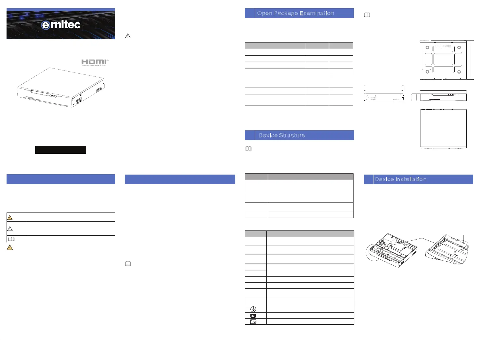
Videooptager
0070-10406
| Mærke: | Ernitec |
| Kategori: | Videooptager |
| Model: | 0070-10406 |
| Vekselstrømsindgangsspænding: | 100 - 240 V |
| Bredde: | 372 mm |
| Dybde: | 315 mm |
| Højde: | 47 mm |
| Vægt: | 5600 g |
| Produktfarve: | Sort |
| Pakkevægt: | 7200 g |
| Antal HDMI-porte: | 2 |
| Ethernet LAN-porte (RJ-45): | 2 |
| Antal USB 2.0-porte: | 2 |
| Antal USB 3.2 Gen 1 (3.1 Gen 1) type-A-porte: | 2 |
| Strømforbrug (typisk): | 15 W |
| Driftstemperatur (T-T): | -10 - 50 °C |
| Maksimal opløsning: | 3840 x 2160 pixel |
| Ethernet LAN-datahastigheder: | 10,100,1000 Mbit/s |
| Knap til nulstilling: | Ja |
| HDD kapacitet: | - GB |
| Antal brugere: | 16 bruger(e) |
| Bæredygtighedscertifikater: | CE, Federal Communications Commission (FCC) |
| Optagelsestilstande: | Event, Manual, Schedule |
| Overholdelse af bæredygtighed: | Ja |
| Bevægelsessensor (video): | Ja |
| Ansigtsgenkendelse: | Ja |
| HDD-grænseflade: | SATA |
| RS-232-porte: | 1 |
| Video optagelsestilstande: | 720p, 1080p |
| Lydudgang: | 1 |
| RS-232 grænseflade: | Ja |
| Understøtter RAID: | Ja |
| Maksimal lagerkapacitet: | 16 TB |
| RS-485-porte: | 1 |
| Antal understøttede HHD'er: | 8 |
| Understøttede opløsninger: | 1920×1080, 1280×1024, 1024×768 |
| eSATA: | Ja |
| Multi-skærm: | Ja |
| RAID-niveauer: | 5, 6,10 |
| Backup funktion: | Ja |
| Video indgangskanaler: | 64 kanaler |
| Indgang båndbredde: | 400 Mbit/s |
| Udgang båndbredde: | 400 Mbit/s |
| VGA (D-Sub) udgangsporte: | 1 |
| Sporing af videotab: | Ja |
| Alarm indgangskanaler: | 16 |
| Alarm udgangskanaler: | 6 |
| Garantiperiode: | 5 År |
| Mennesketæller: | Ja |
Har du brug for hjælp?
Hvis du har brug for hjælp til Ernitec 0070-10406 stil et spørgsmål nedenfor, og andre brugere vil svare dig
Videooptager Ernitec Manualer

6 Oktober 2025
6 Oktober 2025
Videooptager Manualer
Nyeste Videooptager Manualer

25 December 2025
14 November 2025
13 November 2025

11 November 2025

11 November 2025
10 November 2025

9 November 2025

9 November 2025

9 November 2025
8 November 2025