EXSYS EX-44343 Manual
EXSYS
Ikke kategoriseret
EX-44343

| Mærke: | EXSYS |
| Kategori: | Ikke kategoriseret |
| Model: | EX-44343 |
| Bredde: | 120 mm |
| Dybde: | 66 mm |
| Vægt: | 550 g |
| Produktfarve: | Black, Brown |
| Relativ luftfugtighed ved opbevaring (H-H): | 5 - 95 % |
| Driftstemperatur (T-T): | 32 - 131 °F |
| Certificering: | CE, FCC, ROHS, WHQL |
| Effektkrav: | 3.3V |
| Platform: | PC |
| Mac kompabilitet: | Ingen |
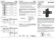
| Kompatible operativsystemer: | Windows 2000/XP/Vista/7/CE 4.2, 5.0/Server 2003, 2008\nLinux 2.4.x, 2.6.x |
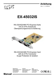
| Værtsgrænseflade: | PCIe |
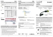
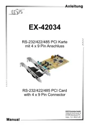
| Stik: | 4x 9-Pin D-SUB M, 1x 25-Pin D-SUB FM, 1x 4-pin |
| Antal serielle porte: | 2 |
| Dataoverførselshastighed: | 0.1 Mbit/s |
| Porte, antal: | 3 |
| Antal parallelle porte: | 1 |
| Chipsæt: | MosChip |
| Understøtter EPP og ECP: | Ja |
Har du brug for hjælp?
Hvis du har brug for hjælp til EXSYS EX-44343 stil et spørgsmål nedenfor, og andre brugere vil svare dig
Ikke kategoriseret EXSYS Manualer
11 November 2025
11 November 2025
11 November 2025
23 September 2025
23 September 2025
24 Juli 2025
24 Juli 2025
24 Juli 2025
24 Juli 2025
23 Juli 2025
Ikke kategoriseret Manualer
- P3 International
- WOOOD
- Soltection
- Yamazen
- Arris
- Bluebird
- Lenco
- Yealink
- Roesle
- Anton/Bauer
- QJ
- Lutron
- Fellowes
- Essentiel B
- Pabobo
Nyeste Ikke kategoriseret Manualer
11 November 2025
11 November 2025
11 November 2025
11 November 2025
11 November 2025
11 November 2025

11 November 2025

11 November 2025

11 November 2025
11 November 2025