EXSYS EX-60326 Manual

| Mærke: | EXSYS |
| Kategori: | bryter |
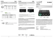
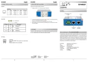
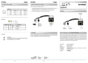
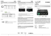
| Model: | EX-60326 |
Har du brug for hjælp?
Hvis du har brug for hjælp til EXSYS EX-60326 stil et spørgsmål nedenfor, og andre brugere vil svare dig
bryter EXSYS Manualer
24 September 2025
4 Juli 2025
4 Juli 2025
4 Juli 2025
6 Juni 2025
2 Juni 2025
1 Juni 2025
1 Juni 2025
1 Juni 2025
bryter Manualer
- Yamaha
- Longshine
- LevelOne
- D-Link
- Intellinet
- Whale
- Mueller
- Crestron
- Philips
- Lorex
- Alcatel
- Cudy
- Adder
- Digitus
- Metra
Nyeste bryter Manualer

4 December 2025

4 December 2025

2 December 2025

2 December 2025

2 December 2025

2 December 2025

2 December 2025

1 December 2025

1 December 2025

1 December 2025