1
USB Plus Matrix Controller • Setup Guide
IMPORTANT NOTE:
Go to www.extron.com for the complete user guide, installation instructions, and specications before connecting the
product to the power source.
The Extron
®
USB Plus Matrix Controller is a pre-congured controller that can easily be setup and deployed to control Extron
USB Extender Plus products in a USB Matrix switching application within a gigabit Ethernet network. Quick and easy setup of the
USB Plus Matrix Controller, USB Extender Plus transmitters and receivers is done using Extron Product Conguration Software (PCS). An
Extron Control System or any third party control can interface with the USB Plus Matrix Controller via Ethernet or RS-232 to perform USB
switching.
The main components in a USB Extender Plus Matrix system:
• USB Plus Matrix Controller — The controller is pre-congured to control the USB Extender Plus transmitters and receivers in a USB
Matrix switching application. The default Telnet port is 22123 (see the USB Plus Matrix Controller Help File for full details).
• USB Extender Plus (transmitters and receivers) — At least 1 transmitter and 1 receiver are required, and up to 64 extenders total
may be included. Each extender must be assigned a unique IP address (DHCP cannot be used to assign these addresses), and these
addresses are uploaded to the USB Plus Matrix Controller. All twisted pair models are supported: rack mountable models (standard and
HID-only), AAP™ models, and decorator-style models (see the USB Extender Plus Series User Guide, available on www.extron.com,
for more information about these models).
• Product Configuration Software (PCS) — This free software is loaded on the computer and is used to congure the USB Extender
Plus transmitters and receivers. It is also used to create a conguration that is uploaded to the USB Matrix Controller (see the
USB Plus Matrix Controller Help File for details on how to use PCS with the USB Matrix Controller).
• Extron Toolbelt — This free software is used to congure the IP settings of the USB Matrix Controller (see the Toolbelt Help File at
www.extron.com for details on how to use Toolbelt).
Installation
ATTENTION:
• Installation and service must be performed by authorized personnel only.
• L’installation et l’entretien doivent être effectués par le personnel autorisé uniquement.
• Do not perform a Mode 5 reset (see USB Plus Matrix Controller Help File) to the USB Matrix Controller. Doing so will erase the
factory loaded configuration used to control the USB Extender Plus transmitters and receivers.
• N’effectuez aucune réinitialisation complète de système (mode 5) (voir USB Plus Matrix Controller Help File) sur l’USB Matrix
Controller. Cette action entraînera en effet la suppression de la configuration par défaut, utilisée pour le contrôle des émetteurs et
récepteurs USB Extender Plus.
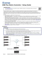
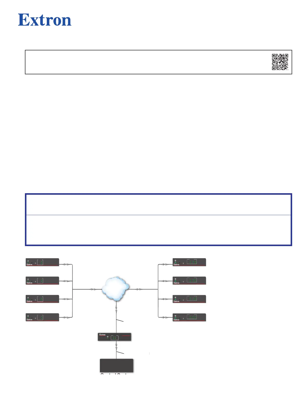
The following diagram shows an example of a USB Plus Matrix Controller system setup:
USB EXTENDER Plus R
CONFIG
PAIR
STATUS
LINK
HOST
1
3
2
4
Rx 1
USB EXTENDER Plus R
CONFIG
PAIR
STATUS
LINK
HOST
1
3
2
4
Rx 2
USB EXTENDER Plus R
CONFIG
PAIR
STATUS
LINK
HOST
1
3
2
4
Rx 3
USB EXTENDER Plus R
CONFIG
PAIR
STATUS
LINK
HOST
1
3
2
4
Rx 4
LAN
1
USB EXTENDER Plus T
STATUS
LINK
HOST
CONFIG
PAIR
2
USB EXTENDER Plus T
STATUS
LINK
HOST
CONFIG
PAIR
3
USB EXTENDER Plus T
STATUS
LINK
HOST
CONFIG
PAIR
4
USB EXTENDER Plus T
STATUS
LINK
HOST
CONFIG
PAIR
USB Plus Matrix Controller
Control System
SIS (Simple Instruction Set Commands)
COM
RTS
CTS
Tx
Rx
R
USB PLUS MATRIX
o
n
ro
y
s
e
r
rix
ontrolle
I
im
le Ins
Control
Figure 1. Application Diagram of the USB Plus Matrix Controller System
1