Fantini Cosmi ECCM32 Manual
Fantini Cosmi
Måleudstyr
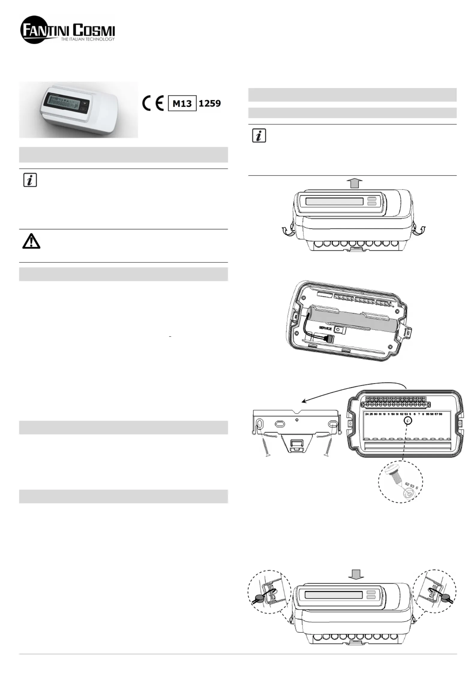
ECCM32
| Mærke: | Fantini Cosmi |
| Kategori: | Måleudstyr |
| Model: | ECCM32 |
Har du brug for hjælp?
Hvis du har brug for hjælp til Fantini Cosmi ECCM32 stil et spørgsmål nedenfor, og andre brugere vil svare dig
Måleudstyr Fantini Cosmi Manualer
8 August 2024
3 August 2024
28 Juli 2024
24 Juli 2024
24 Juli 2024
Måleudstyr Manualer
- Velleman
- Techno Line
- Beckmann & Egle
- SRS
- Rigol
- Kübler
- Brüder Mannesmann
- Milwaukee
- Qualita
- Cliff
- NEO Tools
- LabNation
- Condtrol
- LaCie
- Ideal
Nyeste Måleudstyr Manualer

3 April 2025

3 April 2025

3 April 2025

3 April 2025

3 April 2025

3 April 2025

3 April 2025

3 April 2025

3 April 2025

3 April 2025