Fantini Cosmi ECVCONB Manual
Fantini Cosmi
Måleudstyr
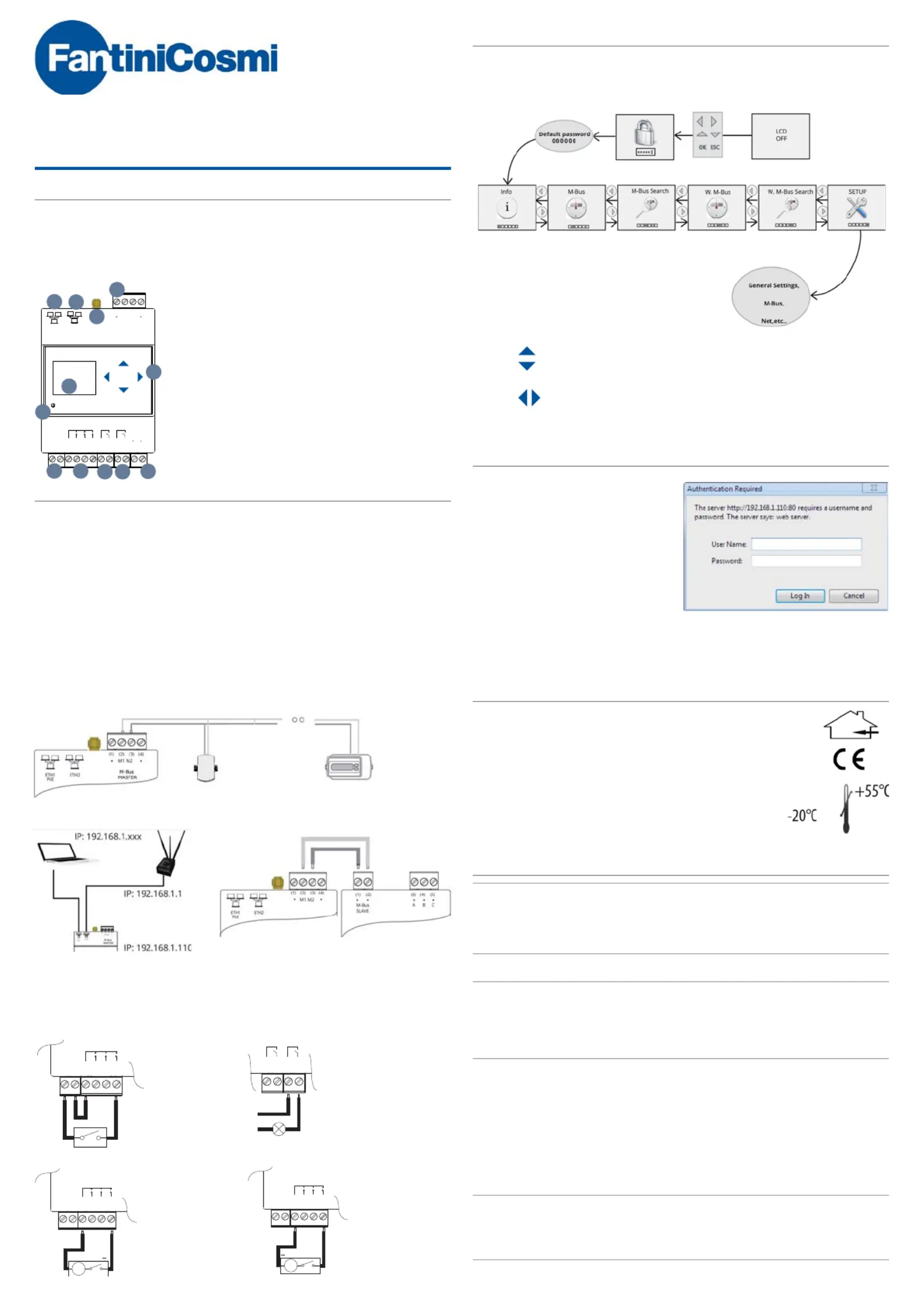
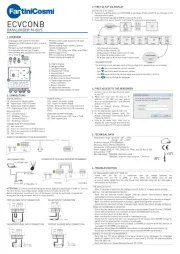
ECVCONB
| Mærke: | Fantini Cosmi |
| Kategori: | Måleudstyr |
| Model: | ECVCONB |
Har du brug for hjælp?
Hvis du har brug for hjælp til Fantini Cosmi ECVCONB stil et spørgsmål nedenfor, og andre brugere vil svare dig
Måleudstyr Fantini Cosmi Manualer
8 August 2024
3 August 2024
28 Juli 2024
24 Juli 2024
24 Juli 2024
Måleudstyr Manualer
- IHealth
- TDE Instruments
- GQ
- Fluke
- Sauter
- Noyafa
- Water-i.d.
- Eastron
- Voltcraft
- Rossmax
- Steinberg
- Meec Tools
- Techno Line
- IFM
- Beurer
Nyeste Måleudstyr Manualer

3 April 2025

3 April 2025

3 April 2025

3 April 2025

3 April 2025

3 April 2025

3 April 2025

3 April 2025

3 April 2025

3 April 2025