Gefen EXT-UHDA-HBT2 Manual
Læs gratis den danske manual til Gefen EXT-UHDA-HBT2 (62 sider) i kategorien AV forlænger. Denne vejledning er vurderet som hjælpsom af 20 personer og har en gennemsnitlig bedømmelse på 4.4 stjerner ud af 10.5 anmeldelser.
Har du et spørgsmål om Gefen EXT-UHDA-HBT2, eller vil du spørge andre brugere om produktet?

Produkt Specifikationer
| Mærke: | Gefen |
| Kategori: | AV forlænger |
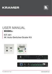
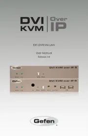
| Model: | EXT-UHDA-HBT2 |
| Type: | AV sender & modtager |
| Produktfarve: | Grå |
| Pakkevægt: | 2000 g |
| Understøttede videotilstande: | 1080p |
| 3D: | Ja |
| Opbevaringstemperatur (T-T): | -20 - 85 °C |
| Relativ luftfugtighed ved drift (H-H): | 5 - 90 % |
| Relativ luftfugtighed ved opbevaring (H-H): | 0 - 95 % |
| HDCP: | Ja |
| Ethernet LAN: | Ja |
| Understøttede lydformater: | LPCM |
| Driftstemperatur (T-T): | 0 - 50 °C |
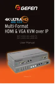
| Maksimal opløsning: | 4096 x 2160 pixel |
| Hurtig start guide: | Ja |
| Kabler inkluderet: | AC, Serial |
| Understøttede grafikopløsninger: | 1920 x 1080 (HD 1080),3860 x 2160,4096 x 2160 |
| Forbindelsesteknologi: | Ledningsført |
| DC-in-stik: | Ja |
| LED-indikatorer: | Ja |
| AC-adapter inkluderet: | Ja |
| Antal USB-porte: | 2 |
| Farvedybde: | 12 Bit |
| Lydindgang: | 1 x TOSLINK, 2 x RCA |
| Modtager vægt: | 350 g |
| Driftsspænding: | 48 V |
| Firmware kan opgraderes: | Ja |
| Maksimal overførselsafstand: | 100 m |
| Ekstern strømadapter: | Ja |
| USB-stik type: | Mini-USB B |
| HSMI-indgang: | 1 |
| RJ-45 indgangs-porte: | 2 |
| Antal HDMI-udgange: | 1 |
| Videoudgang: | 1 |
| Modtager dimensioner (BxDxH): | 214 x 100 x 25 mm |
| Lydudgang: | 1 x TOSLINK, 2 x RCA |
| RS-232 indgangsporte: | 1 |
| Fjernbetjening (IR) indgang: | 2 |
| Fjernbetjening (IR) udgang: | 2 |
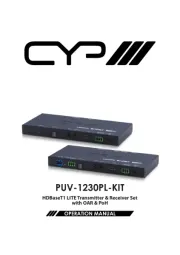
| HDBaseT-port: | Ja |
| RS-232 udgangsporte: | 1 |
| Understøttede kabeltyper: | Cat5e |
| Video indgang: | 1 |
| Senderdimensioner (BxDxH): | 214 x 100 x 25 mm |
| Transmitter vægt: | 350 g |
| Båndbredde: | 300 MHz |
| RJ-45 udgangs-porte: | 2 |
| HDBaseT certificeret: | Ja |
| Understøtter forbrugerelektronik (CEC): | Ja |
| Strømforbrug (modtager) (maks): | 14 W |
| Strømforbrug (sender) (maks): | 14 W |
| IR blaster inkluderet: | Ja |
| IR-modtager inkluderet: | Ja |
Har du brug for hjælp?
Hvis du har brug for hjælp til Gefen EXT-UHDA-HBT2 stil et spørgsmål nedenfor, og andre brugere vil svare dig
AV forlænger Gefen Manualer
AV forlænger Manualer
- Act
- Atlona
- Liberty
- Abus
- Renkforce
- UTEPO
- Apantac
- One For All
- IMG Stageline
- Sescom
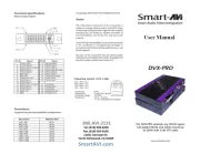
- SmartAVI
- DCU
- Nedis
- CYP
- SWIT
Nyeste AV forlænger Manualer