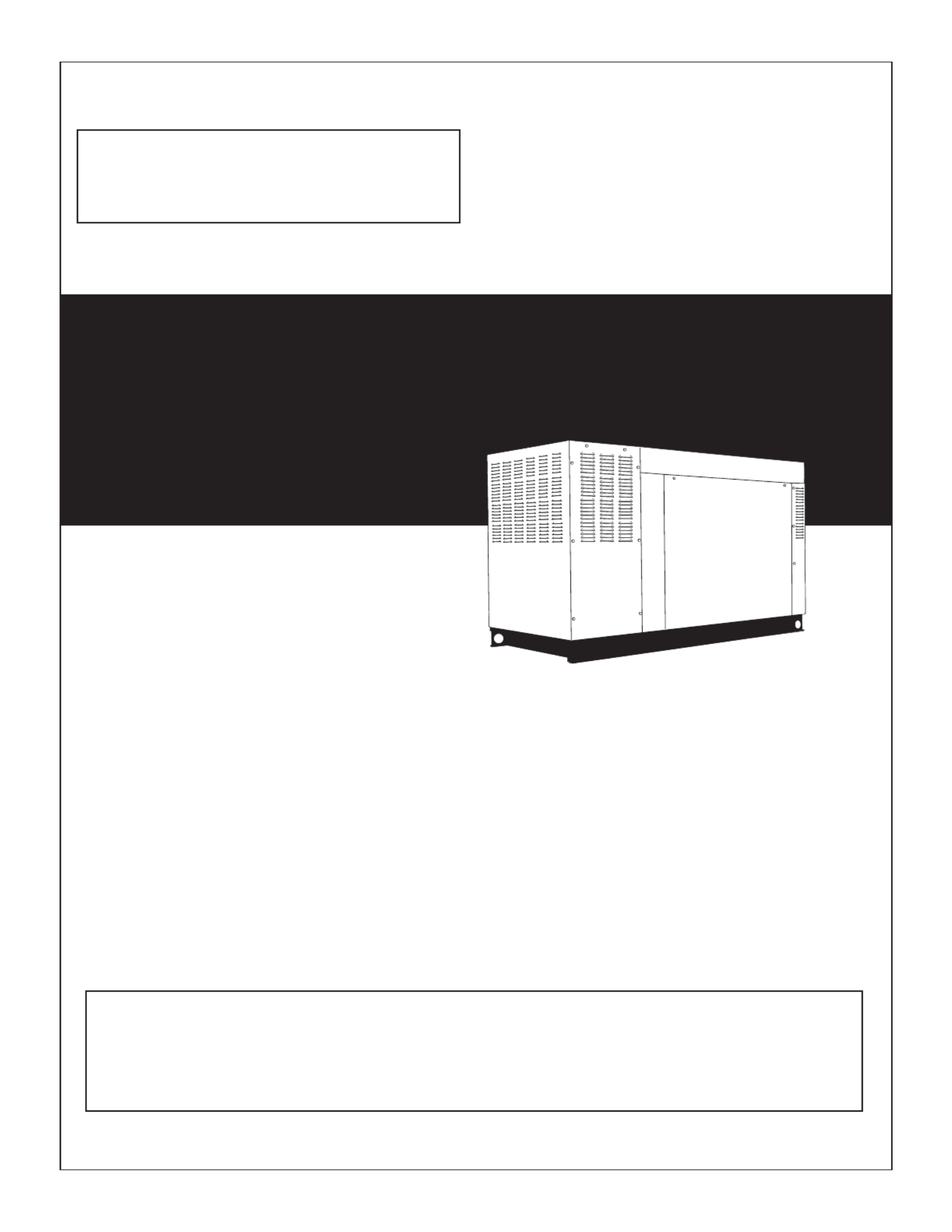
Generac QT03542ANANR Manual


Læs nedenfor 📖 manual på dansk for Generac QT03542ANANR (122 sider) i kategorien Ikke kategoriseret. Denne guide var nyttig for 9 personer og blev bedømt med 4.5 stjerner i gennemsnit af 2 brugere

Side 1/122
STATIONARY EMERGENCY GENERATOR
OWNER'S MANUAL
This manual should remain with the unit.
A new standard of reliability
Serial Number 4.2L
35kW
Models
EPA Certified
Not intended for use in critical life support applications.
ONLY QUALIFIED ELECTRICIANS OR CONTRACTORS SHOULD ATTEMPT INSTALLATION!
DEADLY EXHAUST FUMES. OUTDOOR INSTALLATION ONLY!
— — CAUTION
Cover148 Rev. A 10/08 Part No. 0H0995
Catalog Number OMASPEA035-045-1
1-1
DANGER
 
DANGER
 
1-2
ENGINE PROTECTIVE DEVICES
The Stationary Emergency Generator may be required
to operate for long periods of time without an opera-
tor on hand to monitor such engine conditions as
coolant temperature, oil pressure or rpm. For that
reason, the engine has several devices designed to
protect it against potentially damaging conditions by
automatically shutting down the unit when the oil
pressure is too low, the coolant temperature is too
high, the coolant level is too low, or the engine is run-
ning too fast.
NOTE:
Engine protective switches and sensors are men-
tioned here for the reader’s convenience. Also
refer to the applicable control panel manual for
additional automatic engine shutdown informa-
tion.
HIGH COOLANT TEMPERATURE SWITCH
The switch will close if the temperature should
exceed approximately 140° C (284° F), initiating an
engine shutdown. The generator will automatically
restart and the LED will reset once the temperature
has returned to a safe operating level.
LOW COOLANT LEVEL SENSOR
To prevent overheating, the engine has a low coolant
level sensor. If the level of engine coolant drops below
the level of the low coolant level sensor, the engine
automatically shuts down.
LOW OIL PRESSURE SWITCH
This switch has normally closed contacts that are
held open by engine oil pressure during cranking and
operating. Should oil pressure drop below the 8 psi
range, switch contacts close, and the engine shuts
down. The unit should not be restarted until oil is
added, and the AUTO/OFF/MANUAL switch must be
turned to OFF and then back to AUTO.
OVERCRANK SHUTDOWN
After a prespecified duration of cranking, this func-
tion ends the cranking if the engine has failed to
start. The overcrank LED will turn ON. Turn OFF the
AUTO/OFF/MANUAL switch, then turn switch back to
AUTO to reset the generator control board.
NOTE:
If the fault is not corrected, the overcrank feature
will continue to activate.
Approximate Crank Cycle Times
15 seconds ON
7 seconds OFF
7 seconds ON
7 seconds OFF
Repeat for 45 seconds
Approximately 90 seconds total.
OVERSPEED SHUTDOWN
A speed circuit controls engine cranking, start-up,
operation and shutdown. Engine speed signals are
delivered to the circuit board whenever the unit is
running. Should the engine overspeed above a safe,
preset value, the circuit board initiates an automatic
engine shutdown. Contact the nearest Authorized
Dealer if this failure occurs.
RPM SENSOR LOSS SHUTDOWN
If the speed signal to the control panel is lost, engine
shutdown will occur.
DC FUSES
Fuse F1 (15 amp) is located inside of the control
panel. It protects the panel wiring and components
from damaging overload. Always remove this fuse
before commencing work on the generator. The
unit will not start or crank if the fuse is blown.
Fuse F2 (25 amp) is located in the engine wire har-
ness adjacent to the DC alternator. It is used to pre-
vent circuit failure due to DC alternator falure. If this
fuse is blown, battery charging will not occur while
the engine is running. Replace these fuses with the
same size, type, and rating. (See the exploded views
and parts lists at the end of this manual for replace-
ment part number.)
4-1
Stationary Emergency Generator
Engine Protective Devices
EngProt001 Rev. B 09/08
5-1
6-3
Stationary Emergency Generator
Specifications
GenSpec042 Rev. D 10/08
3. Disconnect the power wires from the fuel sole-
noid located on top of the regulator assembly.
4. Loosen the spring clamp on the small fuel enrich-
ment line and remove the hose from the hose
barb.
5. Remove the black pipe assembly from the outlet
port of the demand regulator.
6. Remove the NG fuel jet (loosen counter clockwise)
from the outlet port.
7. Remove the LP fuel jet (loosen counter clockwise)
from the jet keeper port on the regulator housing.
Install this jet into the outlet port in the regulator
casting.
NOTE:
The jet sizes are stamped on the individual jets.
The larger jet size is used for running on NG.
8. Install the previously removed NG jet into the jet
keeper port on the regulator housing.
9. Install the previously removed black pipe onto
the outlet port of the demand regulator. Use pipe
sealant on pipe threads.
10. Reverse steps 1-4 in this procedure to reactivate
the demand regulator.
11. For LP vapor application, substitute LP fuel inlet
decal for NG fuel inlet decal.
12. The dip switch inside the control panel must be
in the LP or NG position when switching to dif-
ferent fuels (see Control Panel Manual for more
information).
DANGER
Serious injury or damage may occur if not con-
figured properly. Please consult an Authorized
Dealer with any questions.
4.2L IGNITION DESCRIPTION
This single-fire ignition is intended to operate a 6-cyl-
inder, 4.2L, 1800rpm ignition. The 4.2L engine uses
a 36-1 crank sensor, a CAM sensor and coil-on-plug
coils for each spark plug. Engine Timing for the 4.2L,
1800rpm engine is 15 degrees BTDC for both LP and
NG.
The Cam Sensor is factory set to the FULL coun-
ter-clockwise position. Tampering with the posi-
tion of the Cam Sensor could result in engine
failure.
IGNITION POWER-UP INPUT (“56 LINE INPUT)
When battery voltage is applied to this input the igni-
tion will power-up. For the ignition to power itself
down, the battery voltage must be removed from this
input.
DIAGNOSTIC BLINK PATTERNS (RED LED)
During normal ignition operation the RED LED,
located on the ignition control board, flashes at a 0.5
second ON and a 0.5 second OFF rate. This is con-
sidered one (1) blink.
RED LED Fault Codes with priority as shown:
1. Ignition cannot initialize: LED is ON continu-
ously during cranking.
2. Engine Overspeed: LED blinks four (4) times, is
OFF for three (3) seconds and then repeats.
3. No Crank Signal: LED blinks two (2) times, is
OFF for three (3) seconds and then repeats.
4. No Cam Signal: LED blinks three (3) times, is
OFF for three (3) seconds and then repeats.
Only one LED fault code is displayed at a time.
If multiple fault codes exist then the highest priority
fault must be resolved prior to a lower priority fault
code being displayed.
The LED fault code blink pattern is displayed for 60
seconds after a fault and then the ignition will power
itself down.
The Generator must have been in the OFF mode for
60 seconds prior to cranking for the Crank and CAM
LED fault diagnostics to be valid.
The Crank and CAM LED fault codes are not valid
during a re-crank.
NOTE:
The ignition cover does not need to be removed to
see the RED LED
8-1
8-2
Cam Sensor (turn
counter-clockwise)
Cam
Sensor
Stop
Retaining
Washer
10-1
10-5
11-3
Stationary Emergency Generator
Service Schedule
SrvSchd003 Rev. B 10/08
13-1
1 0F3137 1 PAN CB CONN BOX
2 0F3188 1 STAND RH CONTROL
3 0F3189 1 STAND LH CONTROL
4 023484N 1 BUSHING SNAP SB-2.5-31
5 0F6366B 1 XFMR DUAL 120V /16V (F OR 120/240V & 277/480V UNITS)
0F6366A 1 XFMR DUAL 104V/16V (FOR 120/208V UNITS )
6 043180 2 WASHER FL AT M4
7 022264 2 WASHER LOCK #8-M4
8 0C3990 2 SCREW PHTT M4-0.7 X 10 ZYC
(1) 9 057701 REF BLOCK TERM 20A 8 X 6 X 1100V
10 022155 4 WASHER LOCK #6
11 0C2428 4 SCREW PHTT #6- 32 X 1/2 ZY C
12 0F3824 1 DECAL UT IL S ENSE/CUST CONN
13 0A9457 1 DECAL NEUTRAL
14 057073 2 JUNCTION BLOCK 3/8-16
(2) 15 0D5466 REF BUS BAR NEUTRAL BLOCK 390
(2) 16 0A7822 REF LUG SLDLSS 600/250-1/0 X 1/4-28
17 022237 2 WASHER LOCK 3/8
18 022241 2 NUT HEX 3/8-16 STEEL
19 049226 6 WASHER LOCK M5
20 0C2266 6 SCREW PHTT M5-0.8 X 16 ZYC
21 0C2454 8 SCREW THF M6-1 X 16 N WA Z/JS
23 022473 8 WASHER FL AT 1/4-M6 ZINC
24 022097 4 WASHER LOCK M6-1/4
(1) 26 0D4698 REF BLOCK TERM 20A 6 X 3 X 1100V
27 0F4464 1 DECAL CUST CO NN 120V UTILITY
28 025433 1 LUG SLDLS S #6- 14 X 13/64 CU
29 024469 1 SCREW HHTT #10-32 X 3/8 CZ
30 067210A 1 DECAL GROUND LUG
31 0D6029 4 SCREW HHTT M6-1.0 X 16 Z YC
32 081008 1 GROMMET 1.25 X .25 X .75
33 077043J 1 CONDUIT FLEX 2.0" ID (36” LG)
34 051713 2 WASHER FL AT M5
35 0F6156 1 PLATE WIRE SNGL G ALV
36 029289 1 TAPE ELEC 1/2 FO AM (AS REQ’D)
37 047411 4 SCREW HHC M6-1.0 X 16 G8.8
(3) 39 0G0770 1 HARNESS, TRANSFORMER ADAPTER
(4) 40 0H0348 1 ASSY ENCLOSURE PCB 4.2L IGN MD
(4) 41 036943 2 SCREW PPHM #10/32 X 2
(4) 42 023897 4 WASHER FL AT #10 ZINC
(4) 43 022152 2 WASHER LOCK #10
(4) 44 022158 2 NUT HEX #10-32 STEEL
(4) 45 0C2454 1 SCREW THF M6-1 X 16 N WA Z/JS
(4) 46 055934D 1 CLAMP VINYL 1.06 X .406 Z
47 0F6145 A/R SEAL WEATHER .45"DIA
1) UL CIRCUIT BREAKER (ED)
A 0F3328 1 COVER ED CB SHORT STND
C 0D5552 1 CB 0050A 3P 480V S ED4 LL
0D5553 - CB 0060A 3P 480V S ED4 LL
0D5554 - CB 0070A 3P 480V S ED4 LL
0D5556 - CB 0090A 3P 480V S ED4 LL
0D9693 - CB 0125A 3P 480V S ED4 LL
D 0F0492 1 INS ULATOR CB S ( ED-3P)
E 048927 4 SCREW RHM #10-32 X 4- 1/2
F 023897 4 WASHER FL AT #10 ZINC
G 022152 4 WASHER LOCK #10
H 022158 4 NUT HEX #10-32 STEEL
J 0C2454 9 SCREW THF M6-1 X 16 N WA Z/JS
K 029289 1 TAPE ELEC 1/2 FO AM (AS REQ’D)
L 0F1733 1 DECAL CUS TOMER CONNE CT INSIDE
2) UL CIRCUIT BREAKER (FD)
A 0F3138 1 COVER CB CONN BO X
C 0D5572 1 CB 0150A 3P 600V S FD6 LL
0D5573 - CB 0175A 3P 600V S FD6 LL
0D5574 - CB 0200A 3P 600V S FD6 LL
0D5575 - CB 0225A 3P 600V S FD6 LL
0D5576 - CB 0250A 3P 600V S FD6 LL
D 0F0199 1 INS ULATOR CB FD FRAME 30MIL
E 081320 4 SCREW SHC 1/4-20 X 4.5 G8.8 NZ
F 022473 4 WASHER FL AT 1/4-M6 ZINC
G
022097
4
WASHER LO CK M6
-
1/4
H 022127 4 NUT HEX 1/4-20 STEEL
J 0C2454 9 SCREW THF M6- 1 X 16 N WA Z/JS
K 029289 1 TAPE ELEC 1/2 FOAM (AS REQ’D)
L 0F1733 1 DECAL CUSTOMER CONNECT INSIDE
3) UL CIRCUIT BRE AKER (JD+L D)
A 0F3329 1 COVER JD/LD CB SHRT STAND
C 0D5577 1 CB 0300A 3P 600V S JD6 LL
D 0F2353 2 INSULATOR CIRCUIT BR. JD/LD
E 022770 4 SCRE W RHM 1/4- 20 X 3
F 022473 4 WASHER FLAT 1/4-M6 ZINC
G 022097 4 WAS HER LOCK M6-1/4
H 022127 4 NUT HEX 1/4-20 STEEL
J 0C2454 9 SCREW THF M6- 1 X 16 N WA Z/JS
K 029289 1 TAPE ELEC 1/2 FOAM (AS REQ’D)
L 0F1733 1 DECAL CUSTOMER CONNECT INSIDE
4) UL CIRCUIT BRE AKER (QN)
A 0F8135 1 COVER QN FRM CB
C 0E7283 - CB 0150A 2P 240V S QN2 LL
0E7284 - CB 0175A 2P S QN2 LL 240V
D 0E3664 1 BASE, QN CIRCUIT BRE AKE R
E 074908 2 SCRE W HHTT M5-0.8 X 10 BP
F 0F8140 1 COVER QN CB DISH
G 036261 4 RIVET POP .125 X .275 SS
H 0C2454 11 SCREW THF M6- 1X 16 N WA Z/JS
J 029289 1 TAP E ELEC 1/2 FOAM (AS REQ’D)
K 0F1733 1 DECAL CUSTOMER CONNECT INSIDE
(1) ITEM INCL UDED WIT H HARNESS
(2) ITEM INCL UDED WIT H 0D5464B
(3) ITEM USED WITH EARLY MODE L 208V UNITS ONLY
(4) ITEMS USED ON 4.2L MODELS O NL Y.
1 0G68030ST 03 1 WELDME NT RADIATOR SUPPORT C2
2 0F2608A 1 RADIATOR 598 X 568 X 49,CPL L H
3 0E3256 1 V-BELT A58 (60IN O .C.) DDC S60
4 046526 5 WASHER LOCK M10
(1) 5 059981 4 SCREW HHC M10-1.5 X 30 G 10.9
6 0F2776A 1 BRACKET, SIGNAL CONDITIONER (USED ONLY W ITH QTA
PRODUCT)
7 0F5050A 1 SHIELD RADIATOR C4
9 0F2573 1 PULLEY FAN V-GROOVE 9"
10 0F4011 1 FAN COOL 22" DIA 10 BLADE LH
11 0G56820ST 03 1 FLAT TENS IONER ARM
12 0G2990 1 SHO UL DER BO LT 3/8 X 1/2"
13 0F2862 1 S PRING TENSION CPL
14 0F2560 1 P ULLEY V-BELT 4" FLANGED
15 022131 4 WASHER FLAT 3/8- M10 Z INC
16 0E2507 1 PROBE COOLANT LEVEL 3/8NPTF
0H1827 1 PROBE COO LANT LEVEL 3/8-18NPTF (USE WITH I/N 72, P/N
0H1851)
17 035685 2 CLAMP HOSE #28 1.32-2.25
18 0F2561 1 HUB FLEX PLATE
19 0C8145 8 WASHER FLEX (THIN)
20 052250 2 TAPE FOAM 1 X 1 (26.75 LG)
21 0C7043 12 DISK F LEX
23 022473 8 WASHER FLAT 1/4- M6 ZINC
(1) 24 0C8146 4 SCREW HHC 5/16-24 X 1.124
25 022097 16 WASHER LOCK M6- 1/4
26 076749 1 TANK COOLANT RECOVERY
(2) 27 048031C 2(REF) CLAMP HOSE BAND 1/4
28 031971 1 BEARING #6205 2NSE C3 E SRI2 S
29 0F4028 1 PULLEY 6.5" DIA MACHINED
(1) 30 042911 1 SCREW HHC M10-1.5 X 30 G8.8
31 0F2872 1 SCREW HHC 1/2-13 X 2" G8
32 022304 2 WASHER FLAT 1/2 ZINC
33 022195 1 WASHER LO CK 1/2
34 022196 1 NUT HEX 1/2-13 STEEL
35 0F8651 8 SCREW HHFC M8-1.25 X 20 W/M6
36 070015 1 NUT HEX LOCK 5/16-18 NY INS SS
37 0F9867 1 SHAFT FAN DRIVE
38 0F2461 1 RETAINER BEARING
39 022145 15 WASHER FLAT 5/16-M8 Z INC
40 022129 12 WASHER LOCK M8- 5/16
(1) 41 039287 1 SCREW HHC M8-1.25 X 45 C8.8
42 082774 1 KEY WOODRUFF 4 X 19D
43 0G5465 1 HOSE RADIATOR LOWER F RONT
44 0G5459 1 HOSE RADIATOR UP PER F RO NT
45 049813 8 NUT HEX M6 X 1.0 G8 YEL CHR
46 052644 1 SPACER .5 X 1.5 X .25 STL/ZINC
47 0C8566 16 SCREW HHFC M6-1.0 X 20 G8.8
48 0C2454 3 SCREW THF M6-1 X 16 N WA Z/JS
49 090283 1 CAP RADIATOR 13 PS I
50 080713 1 BRACKET COOLANT TANK
51 0G4376 1 WASHER BELLEVILLE .75X.38X.028
52 0G5299 1 COUPLING FLEX HUB MACHINED
(1) 53 049821 3 SCREW SHC M8-1.25 X 30 G 12.9
54 099502 2 CLAMP HOSE #24 B1.06-2.00
61 0C8165 2 NUT HEX LOCK 5/16-24 NY INS
62 051698 1 SCREW HHC M8-1.25 X 75 C8.8
63 049820 3 NUT HEX LOCK M8-1.25 NY INS
64 0G6793AST03 1 BRACKET TENSIONER SPRING
65 039253 2 SCREW HHC M8-1.25 X 20 C8.8
66 0G56830ST03 1 TENSIO NER ARM SUPPORT BENT 90
67 022145 1 WASHER FLAT 5/16-M8 Z INC (USED ONLY WITH QTA
PRODUCT)
68 022129 1 WASHER LO CK M8- 5/16 ( USED ONLY WITH QTA PRODUCT)
69 0F8651 1 SCREW HHFC M8-1.25X20 W/M6 (USED ONLY WIT H QT A
PRODUCT)
70 029032 1 HO SE 9/32 ID (60 LG)
71 029333A 10 TIE WRAP UL 7.4 X .19” BLK (NOT SHOWN)
72 0H1851 1 ASSY PCB LCL SENSOR (USE WITH I/N 16, P/N 0H1827 ONLY)
(1) APPLY MEDIUM STRENG TH BLUE THREAD LOCKING FLUID
TO THREADS.
(2) INCLUDED WITH I/N 26.
BEARING PRESS NOTE:
APPLY LOCTITE 620 BEARING RETAINMENT CO MPOUND TO
BEARING SURF ACE ON ITEM 37 PRIOR TO PRESSING ITEM 28
ONTO ITEM 37.
ALSO APPLY LOCTITE 620 BEARING RETAINMENT COMPOUND
TO THE OUTSIDE OF 28 PRIOR TO INSTALL ING ITEM 28 INTO
IT EM 38.
1 026915 2 NIPPLE CLOSE 3/4 X 1.375
2 075580 1 FLANGE FUEL INLET
3 0F6390E 1 REGULATOR ASSY 4.2L 48KW
0F6390F 1 REGULATOR ASSY 4.2L 35KW
4 039253 2 SCREW HHC M8-1.25 X 20 G8.8
5 022145 2 WASHER FLAT 5/16-M8 ZINC
6 022129 2 WASHER LOCK M8-5/16
7 045771 2 NUT HEX M8-1.25 G8 CLEAR ZINC
9 0E8286 1 STREET EL 45D 1/2 NPT BRASS
10 026812 2 ELBOW 90D 3/4 NPT
11 0F8379 1 NIPPLE PIPE 3/4 NPT X 7
13 057823 2 CLAMP HOSE #10 .56 - 1.06
14 059057 1 HOSE 3/4 ID SAE-30R2 (22” LG)
15 047527 1 BARBED STR 1/2 NPT X 3/4
16 0D1509 1 DECAL INLET PRESSURE
17 050279 1 DECAL FUEL INLET NG (NATURAL GAS APPLICATION)
050280 1 DECAL FUEL INLET LPG (LP VAPOR APPLICATION)
18 0F2119 1 O-RING 45.63 ID X 2.62 WIDTH
19 0E6586 1 GASKET BOSCH 32
20 0E4394 1 ACTUATOR BOSCH 40 GOVERNOR
21 040105 1 HOSE COOL 2 IN ID 20R4
22 0G4573B 1 MIXER ACTUATOR 40MM MACHINED
23 0F7790E 1 VENTURI THROTTLE 26MM
24 0E7121 1 O-RING 47.625 ID X 2.38 WIDTH
26 022097 8 WASHER LOCK M6-1/4
27 046580 4 SCREW SHC M6-1.0 X 45 G12.9
28 035685 2 CLAMP HOSE #28 1.32-2.25
29 0F6155 1 HARNESS CPL FUEL JUMPER
30 047290 1 HOSE 3/8 ID SINGLE BRAID (20” LG)
31 0E6123A 1 INTAKE ADAPTER 4.2L G3-BOSCH
32 048031J 2 CLAMP HOSE BAND .63
33 0G1462 1 HOSE BARB REDUCER 5/8"-3/8"ID
34 048031P 2 CLAMP HOSE BAND .88"
35 0G0321 1 HOSE COOL 5/8"ID 250#WP (2”LG)
36 047487 4 SCREW SHC M6-1.0 X 18 G12.9
RECONFIGURING THE FUEL SYSTEM
Note: All models are configured to run on natural gas from the factory.
To reconfigure the fuel system from NG to LP, follow these steps:
1. Turn the main gas supply off.
2. Remove the carburetor fuel hose from the outlet port of the demand regulator (See Detail “A”).
3. Disconnect the power wires from the fuel solenoid located on top of the regulator assembly.
4. Loosen the spring clamp on the small fuel enrichment hose and remove the hose from the hose barb.
5. Remove the black pipe assembly from the outlet port of the demand regulator.
6. Remove the NG fuel jet (loosen counter clockwise) from the outlet port.
7. Remove the LP fuel jet (loosen counter clockwise) from the jet keeper port on the side of the regulator housing.
Install this jet into the outlet port in the regulator casting.
Note: The jet sizes are stamped on the individual jets. The larger jet size is used for running on NG.
8. Install the previously removed NG jet into the jet keeper port on the side of the regulator housing.
9. Install the previously removed black pipe onto the outlet port of the demand regulator. Use pipe sealant on pipe
threads.
10. Reverse steps 1-4 in this procedure to reactivate the demand regulator.
11. For LP vapor application substitute LPG fuel inlet decal p/n 050280 for NG fuel inlet decal p/n 050279 (Item 17).
12. When switching fuel types, the proper dip switch settings must be made to the control panel. See owners
manual, fuel section, for more details.


Produkt Specifikationer

Mærke: Generac
Kategori: Ikke kategoriseret
Model: QT03542ANANR

Har du brug for hjælp?

Hvis du har brug for hjælp til Generac QT03542ANANR stil et spørgsmål nedenfor, og andre brugere vil svare dig


Ikke kategoriseret Generac Manualer

Generac

Generac 6852 Manual

6 September 2024
Generac

Generac CW20 Manual

6 September 2024
Generac

Generac XC3000P Manual

6 September 2024

Ikke kategoriseret Manualer

Nyeste Ikke kategoriseret Manualer