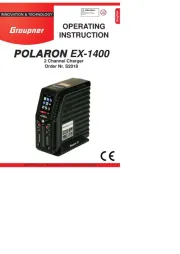
Graupner Polaron EX1400 Manual
Graupner
Batterioplader
Polaron EX1400
Læs gratis den danske manual til Graupner Polaron EX1400 (56 sider) i kategorien Batterioplader. Denne vejledning er vurderet som hjælpsom af 50 personer og har en gennemsnitlig bedømmelse på 4.4 stjerner ud af 25.5 anmeldelser. Har du et spørgsmål om Graupner Polaron EX1400, eller vil du spørge andre brugere om produktet?
Side 1/56

OPERATING
INSTRUCTION
English
GRAUPNER/SJ GmbH • Henriettenstr.96, D-73230 KIRCHHEIM/TECK GERMANY
INNOVATION & TECHNOLOGY
POLARON EX-1400
2 Channel Charger
Order Nr. S2018

2 3
English
2 3
Introduction .......................................................3
Symbols explanation ........................................4
Safety instructions ............................................5
Notes on batteries handling .............................6
Capacity and use time ..................................7
Disposal of waste batteries ..........................7
Environmental information ...............................8
General operating information ..........................8
Declaration of Graupner|SJ GmbH ...............10
Intended use ................................................... 11
Care and maintenance ................................... 11
Package content .............................................12
technical specications ..............................13
Operating elements ........................................14
Commissioning ...............................................15
Basic operations .............................................16
Control buttons ...........................................17
Menu PROFILE ..............................................17
Menu CHARGE ..............................................18
Adjustable Parameters ...............................19
Charge modes of different battery types ....21
Menu DISCHARGE ........................................24
Adjustable Parameters ...............................24
Discharge modes .......................................25
Menu CYCLE..................................................28
Adjustable Parameters ...............................28
Menu BALANCE .............................................33
Menu DATA .....................................................35
Menu TOOLS .................................................37
Submenu “SERVO“ ....................................37
Submenu “MOTOR“ ...................................38
Submenu “HEATING“ .................................40
Submenu “E.S.C“ .......................................41
Menu SETTINGS............................................43
Menu STORAGE ............................................44
<Factory settings> ..........................................45
Display “1. Factory reset“ ...........................45
Display “2. Display calibration“ ...................45
Display “3. Resource Update“ ....................46
Display “4. BLC Port Test“ ..........................46
Firmware update.............................................47
Alert messages ...............................................48
Troubleshooting ..............................................51
Declaration of conformity ................................54
Warranty .........................................................55
Content table

English
INNOVATION & TECHNOLOGIE
2 32 3
Introduction
Thank you for choosing a Graupner Polaron charger. This charger is extremely powerful and can
be used by both beginners and experts.
Please read this manual carefully to get the best results with your charger and charge your bat-
teries safely. If you experience any trouble during operation, take the manual for help or ask your
dealer or Graupner service center.
Due to technical changes, the information in this manual may be changed without prior notice.
This product complies with national and European legal requirements.
To maintain this condition and to ensure safe operation, you must read this manual and all
safety instructions before using the product!
NOTE
This manual is part of this product. It contains important information concerning
operation and handling. These instructions have to be stored securely and in case
of transfer of the product they should follow it by the next owner.
All company and products names are trademarks of their respective owners.
All rights reserved.
For technical questions, please contact our customer service, see page 55.
!
DANGER!
Before operating your new charger be sure to read the instructions completely.
Please follow the instructions for disposal and environmental protection on page 8.

English
4 5
Symbols explanation
!
ATTENTION!
This symbol highlights the nearby and following instructions, which must be ob-
served by the user! Any disregard these warnings can affect the safe operation
and the safety of the operator.
!
This symbol WITHOUT specic heading highlights the nearby and following notes
and tips, which should be strictly observed by the user! A breach of these notes
and tips can result in damages of any kind.
!
WARNING
This symbol highlights prohibitions which must be strictly observed by the user!
Any failure to comply with these restrictions may affect the viability and safety of
the operator.
P
CARE AND MAINTENANCE
This symbol highlights notes produced for the care and maintenance of the prod-
uct, which should be strictly observed by the operator to ensure long life of the
product.
NOTE
This symbol highlights instructions, which should be strictly observed by the ope-
rator to ensure safe operation of the unit.
TIP
This symbol highlights tips and experiences out how you can avoid potential prob-
lems or damage and provides assistance to resolve any issues.
DISPOSAL INSTRUCTIONS
This symbol highlights the following points as individual materials or products
must be necessarily disposed of by the users!

English
INNOVATION & TECHNOLOGIE
4 5
Safety instructions
!
ATTENTION!
• Damage caused by failure to comply with these instructions will invalidate the
warranty / guarantee. For further damages we do not assume any liability!
• We do not assume any liability for damage to property or personal injury caused
by improper use or non-observance of safety instructions!
• The charger must be protected from dust, moisture, rain, heat (as sunshine) and vibra-
tion. Only to be used in dry conditions!
• The case slots serve to cool the charger and must not be blocked or covered. The unit
must be installed so that the air can circulate freely.
• Do not plug more than one charger into a power strip! It may produce acute danger of
line congestion and consequently re!
• The charger has to be connected to a 12 V or 24 V car battery or to a suitable stabilized
power supply with 11 ... 28 V DC output. Never connect an AC voltage on the DC input!
There is a serious risk of re!
• No change-ups may be performed.
• The charger and the battery to charge must be placed during operation on a non-am-
mable, heat-resistant and electrically non-conductive pad! Do not place directly on car
seats, carpets or similar! Also ammable or highly ammable materials must be placed
away from the charging station. Ensure good ventilation.
• Batteries may explode and / or burn through a defect!
• Connect the charger with the original connection cables and terminals directly to the car
battery. As long as the charger is connected to the car battery, the car engine MUST be
off! The car battery cannot be charged simultaneously from another charger!
• Between the charging ports and the vehicle body it is possible to have battery short cir-
cuit! Therefore, never use the charger directly to the vehicle body.
• The charge output and connecting cables must not be modied or connected to each
other in any way. Charging and connecting cable must not be wound up during opera-
tion!
• Do not leave the charger unattended when connected to the power supply.
• Operate your charger only in rooms with a smoke detector.
• Connect only a battery that has to be charged to respective charging port.
• The following batteries must not be connected to the charger:
○ NiCd / NiMH batteries with more than 16 cells, LiFe / Li-Ion / LiPo batteries with more
than 8 cells, lead-acid batteries with more than 12 cells.
○ Batteries which require a different charge method from NiCd, NiMH, lithium or lead-ac-
id batteries.
○ Defects and / or damaged cells or batteries.
○ Batteries connected in parallel or with different cells.
○ Mixed batteries with old and new cells, or cells with different features.
○ Non-rechargeable batteries (dry cells). There is a serious risk of explosion!

English
6 7
○ Batteries and / or cells that are not expressly approved by the manufacturer for the
charging currents occurring during charging with this charger.
○ Already fully charged or hot, or not completely empty cells or batteries.
○ Batteries or cells with integrated charging or disconnecting device.
○ Batteries or cells that are installed in a device or that are electrically connected to oth-
er components.
• To avoid short circuits between the banana plugs tted to the charge leads, please al-
ways connect the charge leads to the charger and only then to the battery! When discon-
necting, proceed in reverse order.
• When charging a transmitter, an interruption of charge can - even for short periods -, let
the charge voltage rise in such a way that the transmitter is destroyed by the overvoltage
immediately. Risk of re!
Notes on batteries handling
•
!
Batteries, and also individual cells are not toys and should be kept out of the
reach of children.
Before each use, check the proper condition of the battery. Do not use defective
or damaged cells / batteries.
• Overcharging and deep discharge lead to irreparable damage to the cells and damage
permanently the capacity of the battery.
• Never store batteries uncharged, discharged or partially charged for long periods. Be-
fore storing batteries charge them and from time to time check charge status. NiMH cells
should be 1 V per cell and Lilo / LiPo cells should never be less than 3 V per cell, in order
to achieve an optimum service life.
• Overcharging also damages the capacity of the battery. Therefore do not charge any hot
or charged batteries again.
• High power charge and discharge shorten the life expectancy of the battery. Therefore,
do not exceed the rates stated by the manufacturer.
• Lead-acid batteries are not high power rechargeable. Never exceed the maximum charge
rate stated by the battery manufacturer.
• When buying batteries ensure good quality, rst charge new packs at low rates, and work
up gradually towards higher currents.
• Charge the battery just before you want to use them, the batteries are at their most pow-
er.
• Rechargeable batteries / cells must not be heated, burnt, short-circuited or overloaded
with excessive or reversed polarity currents.
• Batteries cells connected in parallel with combination of old and new cells, different fea-
tures as capacity and voltage, made by different manufacturers, brands or types should
not be used.
• A built-in battery in a device should be removed whenever the device is not used. Always
turn off equipment after use to avoid deep discharge. Recharge the batteries just for the
right time.
• The battery to charge should be placed when charging on a non-ammable, heat re-
sistant and non-conductive pad! Also ammable or highly ammable materials must be
placed away from the charging station.
• Batteries must be charged only under supervision. Observe the maximum specied
charge rate for the specic cell type. Charge current must never be exceeded.
• Should the battery heat during charge to more than 60 ° C, the charge must be stopped
immediately and the battery must be cooled to about 30 ° C.
• Never charge batteries that are hot or not discharged to the rated discharge voltage.

English
INNOVATION & TECHNOLOGIE
6 7
• No changes should be made to the batteries. Never solder or weld directly to the cells.
• Released electrolyte is corrosive, not allow contact with skin or eyes. In an emergency,
rinse immediately with plenty of water and then consult a doctor.
• Suitable extinguishing media are extinguishing blankets, CO2 estinguishers and sand.
• The valve openings of the cells must not be blocked or sealed in any case, for example
by soldering. When soldering do not exceed a temperature of 220° C and for a period not
longer than 20 seconds.
• To avoid deformation, do not produce an excessive mechanical pressure.
• If a battery is overheated, proceed as follows:
Disconnect the battery and place it on a non-combustible surface (stone oor) until it has
cooled. Never keep the battery in your hand to avoid the risks of re and / or explosion.
• Protect batteries from vibration, and do not expose to mechanical stresses.
• When charging and during operation of the batteries, they can generate explosive gas
(hydrogen), be careful with adequate ventilation.
• Never short circuit the batteries. This might cause re and / or explosion!
• Batteries may explode or burn through a defect. We therefore recommend that all lithium,
NiCd and NiMH batteries, should be charged in a LiPo safety case Order Nr. 8370 or 8371.
• Do not open batteries, chemical burn danger.
• NiCd or NiMH battery packs perform their best by rst individually all cells are dis-
charged separately and only then the entire battery pack is charged. Discharging should
be done by the charger cell by cell.
• Make sure that the charge-discharge are done properly.
•
Charging single NiCd or NiMH cells or batteries with 1 ... 4 cells, can be difcult
for the automatic shut-off. Since the onset after the full load point voltage drop is
not very pronounced, the automatic shut-off cannot or do not respond properly.
The correct operation cannot be guaranteed in this case. Be sure to check through multi-
ple, monitored test charges, if a proper shutdown occurs for the batteries you are using.
There is a serious re and / or explosion risk!
Capacity and use time
For all current sources applies: The capacity decreases with every charge. At low temperatures
the internal resistance increases reducing the capacity. As a result, the ability to provide power and
holding the voltage can be reduced.
Frequent charging and / or discharging programs can also lead to a gradual reduction in capacity.
However, current sources should be reviewed at least every 6 months on their capacity, and re-
place them if there is a signicant loss of capacity.
Use only genuine Graupner batteries!
Disposal of waste batteries
Every consumer is legally obliged under the German battery ordinance to return all used
and exhausted dry and rechargeable batteries.
Disposal in the household waste is prohibited. Old batteries can be brought to the public
collection points or given at our retail outlets and wherever batteries of the same type are sold. You
can return used batteries sent by us to the following address:
Graupner|SJ GmbH
Service: Gebrauchte Batterien
Henriettenstrasse 96
D-73230 Kirchheim unter Teck
You make a signicant contribution to environmental protection!

English
8 9
!
DANGER!
Damaged batteries need a special packaging for shipping because they are very
toxic!!!!!
Environmental information
DISPOSAL INSTRUCTION
This symbol on the product, user manual or packaging indicates that this product must
not be disposed of with other household waste at the end of its life. It must be handed
over to the applicable collection point for the recycling of electrical and electronic equip-
ment.
The materials are recyclable as marked. By material recycling or other forms of re-usage you are
making an important contribution to environmental protection.
Batteries and accumulators must be removed from the device and disposed of at an appropriate
collection point.
Please inquire if necessary from the local authority for the appropriate disposal site.
General operating information
• When charging the battery it is supplied a certain amount of electricity, which results from multi-
plying charge current by charge time. The maximum amount of power depends on the capacity
of each battery and the maximum charge current according to the battery type. Both values are
given in the specications of the battery manufacturer.
Only when explicitly rated, fast rechargeable batteries can exceed the normal charging
rate. As STANDARD CHARGE CURRENT, is referred to the 1/10 of nominal capacity: (1/10
C) for a battery with a capacity of 1700 mAh the standard charge current is 170 mA.
• The battery should be connected using a suitable charger cable to the connection terminals of
the charger (red = positive, black = negative). Use only original charging cable with sufcient
cross-section.
• Always follow and observe the recommended charge currents and charge times as rated in the
instructions of the battery manufacturer. Only batteries which are expressly suitable for quick
charge can be charged with the high charging currents provided by this charger.
• Please keep in mind that new batteries reach their full capacity after several charge / discharge
cycles. Some new or deep discharged batteries may also have premature charge termination.
• Should, after a fast charge, a cell of the NiXX battery packs have become particularly hot, this
may indicate a defect of that cell. This battery pack should no longer be used! (Used batteries
have to be disposed of as special waste!).
• Since the charger can only detect the total resistance, but does not distinguish between internal
resistance of the battery, cable resistance and connector transfer resistance, the rst require-
ment for a proper function is a charging cable with sufcient cross-section and a length of not
more than 30 cm with high performance connectors (gold contacts).
• A transmitter built-in battery can be charged via the tted charge socket.
• Transmitters are often included with a reverse current protection in the form of a diode. This pre-
vents damage for the transmitter from reverse polarity and short circuit between the bare ends
of the charging cable connector. Depending on the design of this diode CAN however even
hinder a correct recognition of the state of charge by the automatic charger.
• The maximum allowable charge current for the transmitter must never be exceeded.
• To prevent internal damage to the transmitter due to overheating due to a fast charge, the trans-
mitter battery should be removed from the transmitter battery compartment.
• The transmitter MUST be switched „OFF“ (OFF) during the charging process!
• Never turn on the transmitter when it is connected to the battery charger.
• Do not discharge the battery through maintenance programs via the charge socket!

English
INNOVATION & TECHNOLOGIE
8 9
The charge socket is not suitable for this use.
• The charger sets the required charging current only as long as the technical possibilities of the
charger are not exceeded! Should it be provided a charging current that the charger technically
cannot afford, the value will be automatically reduced to the maximum possible value. In this
case, the actual charge current will be shown in the display.
• Make sure to check after a „nish“ message that the displayed charge rate shown by the unit is
the same you expected. So you can recognize reliable and timely incorrect shutdown. The pro-
bability of false indications depends on many factors, most likely with deep discharged batteries,
low cell counts and particular cell types.
• Make sure, by several test charges, especially on low cell numbers, of the proper function of the
automatic shut-off. Under certain circumstances, fully charged batteries are not detected by a
weak peak, resulting in re and / or explosion hazard!
• The charger might not detect automatically the connected battery type, LiPo or NiMH, in this
case the battery type and the appropriate charge mode must be selected manually! Conse-
quently, please be sure to check before charging: Is this the appropriate charge program, the
correct charging current is set? Failure to comply may result in re and / or explosion!
• Are all connections securely rm, or is there an intermittent contact? Please keep in mind that
the rapid charging of batteries may be dangerous. A break, even for a short time, for example
due to an intermittent contact, leads inevitably to malfunctions, may trigger a restart of the char-
ge and totally overloaded the pack. This represents a re and / or explosion risk!

English
10 11
Declaration of Graupner|SJ GmbH
Content of the Declaration
If there are defects in material or workmanship for one of acquired object sold by us or by our
dealer in the Federal Republic of Germany (§ 13 BGB) we, Graupner/SJ GmbH, Kirchheim/Teck
provide in following circumstances the removal of defects for this item.
Graupner/SJ GmbH assumes no liability for non-approved parts or accessories from other
manufacturers and cannot judge all third party product, whether it can be safely used.
The consumer cannot claim rights under this declaration if there is impairment of the usability of
the product due to natural wear, use under competition conditions, misuse (including installation)
or external inuences.
This declaration does not affect the legal or contractual rights regarding arising defects and defects
rights of the consumer for the purchase contract between him/her and the vendor (dealer).
Extent of Warranty
Both the adherence to the operating instructions as well as the conditions and methods of instal-
lation, operation, use and maintenance of this charger are not monitored by Graupner/SJ GmbH.
Therefore Graupner/SJ GmbH accepts no liability for any loss, damage or expense arising from
the improper use or operation in any way.
In case of warranty we provide at our choice to repair or replace the defective goods.
Further claims, in particular claims for reimbursement of costs associated with the defect and the
compensation for consequential damages (installation/removal costs) are - where allowed by law -
excluded. Claims on legal regulations, especially under product liability law remain unaffected.
Guarantee requirements
The buyer has to make the guarantee claim in written form, enclosing the original proof of pur-
chase (as invoice, receipt, delivery note) located on the inside back cover guarantee card. He must
send the defective goods to us at his own cost to the following address.
Firma Graupner/SJ GmbH, Serviceabteilung,
Henriettenstr. 96, D-73230 Kirchheim/Teck
The purchaser should state the material or workmanship or the symptoms of the fault so concrete
that we can check if our guarantee obligation is applicable.
The transport of the defective object from the consumer to us and repatriation is a risk of the con-
sumer.
Period of validity
This statement is valid only during the claim period for us asserted claims from this declaration.
The claim period is 24 months from date of purchase by the consumer from a dealer in the Federal
Republic of Germany (date of purchase). If defects are evidenced after the claim period or if re-
quired evidence or documents for the recovery of defects as under this declaration, are submitted
after the expiry of the claim period, then the buyer has no right or claims from this declaration.
Limitation
If we do not recognize a properly asserted within the claim period, all claims from this declaration
after 6 months from the date of the establishment shall be barred, but not before the end of the
claim period.
Applicable law
Claims, rights and obligations resulting from this declaration are only valid to the pertinent German
Law, without the rules of private international law, so as the UN Sales Convention.

English
INNOVATION & TECHNOLOGIE
10 11
Intended use
The Graupner Polaron EX-1400 you have acquired is a professional product with superior proper-
ties. By using advanced semiconductor technology and a powerful microprocessor with superior
charging characteristics, simple operation and optimum reliability are achieved.
With the Graupner Polaron EX-1400 it is possible to charge all model batteries such as: Nickel
Cadmium (Ni-Cd), Nickel-Metal Hydride (Ni-MH), Lithium Polymer (LiPo), Lithium Ion (Lilo), Lithi-
um Iron (LiFe), Lead-Gel and Lead-acid (Pb).
Connect the charger to a car battery or preferably to a power supply with a stabilized direct current
output of 12 ... 24 V and 25 A output power (recommended Order Nr. S2012). Please note: If the
supply voltage drops below 23 V, the maximum possible power of the charger is not reached (see
also section „Technical specications“ on page 13).
NOTE
It is important to observe the charge instructions of the battery manufacturer and observe
the recommended charge currents and charge times. Only batteries which are expressly
suitable for high charge currents should be charged quickly! Please keep in mind that new batter-
ies do eventually reach their full capacity after several charge/discharge cycles, and can result in
premature charge cutoff. Make sure after several charges of the proper and reliable operation of
the automatic charge termination circuit and the charged capacity.
!
ATTENTION!
Obey all safety messages in this manual. They contain important information on handling
the product. You are responsible for the safe operation of the product! Not following the
manual and safety instructions will void the warranty.
They are required different connectors with several requirements in the use and application of
rechargeable batteries of different kind. Note that connectors, connector names and polarities of
other manufacturers may be different. Therefore, use only genuine matching connectors of the
same design.
Also, use only original charging cable with sufcient cross-section.
Care and maintenance
P
The charger is maintenance-free and requires no maintenance. However, please protect it
in your own interest from dust, dirt and moisture!
Disconnect the car battery and battery for cleaning the charger, and use only a dry cloth
lightly rub (do not use cleaning agents).

English
12
13
Package content
The set includes:
• Graupner Polaron EX-1400 Charger
• 2x EH to XH 8S Adapter boards and 8S cable
• USB cable (USB-A to mini-B-USB 5poles)
• 1 Input cable
• 2 Temperature sensors
• 2 charge cables
• 2 crocodile clips
• 1 charger stand
• Operation manual

English
INNOVATION & TECHNOLOGIE
12 13
* Information for each battery terminal
technical specications
Charger and power supply in general
Display 3.0 „Color TFT LCD Touch Screen
Operating voltage range 11 ... 28 V DC (direct current)
Required car battery 12 or 24 V with at least 60 Ah capacity
Required power supply 12 ... 28V DC with at least 25A
Suggested power supply polaron power supply 12V DC 25A, Order Nr. S2012
Maximum charging power ...
... At 12 V supply voltage 700 W
... At 24 V supply voltage 1400 W
Undervoltage cutoff 10.7V
Safety timer 10 ... 900 mins, off
Weight about 1485 g with Stand
Dimensions (W x D x H) 88.2 x 203.4 x 196,3mm
Connections
Battery ports 2, independently settable
Charging current / power per port 0.1 ... 30 A / max. 560 W at 28 V supply voltage
Discharge currents / power per port 0.1 ... 10 A / max. 60 W
Battery memory per port 20 memories
USB charging port B-Type, 5 V and max. 2.5A Output Power
Balancer port Graupner / EH, 1 ... 8 LiPo / Lilo / LiFe cells
Temperature sensor 10 ... 80 ° C / 50 ... 176 ° F
Charge distribution by default 50% / 50%
Ni-Cd & Ni-MH batteries*
Cell number 1 ... 16 cells | charge, discharge cycle
Charging process automatic, normal, linear
Delta-peak NiCd 5 ... 25 mV / cell, NiMh 3 ... 15 mV / cell
Trickle charging Off, <500 mA, automatic (1/20 of the charge current)
Cycles 1 ... 10 cycles, wait time adjustable 1 ... 30 min
Adjustable Direction Charge → discharge, discharge → charge
Adjustable capacity range 10 ... 150%
Lithium batteries*
Cell number 1 ... 8 cells | Charge, discharge, storage mode
Charging method normal, fast
Cell voltages 3.3V (LiFe), 3.6 V (Lilo) and 3.7 V (LiPo)
Adjustable capacity range 10 ... 120%
Charge rate 1 ... 5C
TCS capacity 10 ... 100%
Balancing current max. 1000 mAh
Lead batteries*
Cell number 1 ... 12 cells | charge, discharge
Cell voltage 2V

English
14 15
Operating elements
8
8
Back sightFront sight
3
4
5
1
2
7
6
Nr. Description
1 3.0 "Color TFT LCD Touch Screen
2 LED indicators for charge / discharge
3 Push button to switch between CH1 and CH2
4 Charge / discharge status bar
5 Battery port
6 Balancer port
7 Port for temperature sensor
8 XT90 connector to connect the power supply to the charger
9 Fans
10 Lateral docking jacks for separately sold AC adapter, Order Nr. S2012
!
ATTENTION!
• If the Graupner Polaron EX-1400 is connected through the XT90 connector, located
on the back, to an external power source, such as a car battery, there is current on the
other plugs, located on the side (red on the bottom front part and black on the upper back part).
Never connect these jacks one another!!!
• Disconnect the docked Polaron power supply 12 V DC 25 A, Order Nr. S2012, from the charger
Polaron EX-1400 before you connect the charger to any other external power source. Other-
wise, the power supply load on the charger docking connection plugs will be added unnecessa-
rily to the external power source.
• Never shortcircuit the two charge ports.
• Never connect two separate, but interconnected to the negative poles battery packs, to both
charge ports.
8
9
10
10

English
INNOVATION & TECHNOLOGIE
14 15
Right side sightUpper sight
Nr. Description
11 Mini-USB connector for resource and rmware updates, see pages 46 and 47, and for
reading out data via PC or laptop using the “PC software” available for Polaron chargers
in the download area of the product.
12 USB charging plug 5V / 2.5A (Not suitable for connection of PC or Laptop!)
13 Connection for external modules, see page 41
14 Connection for sensors of brushless motors, see page 37
15 Connection for servo test function, see page 37
Commissioning
Connect the Graupner Polaron EX-1400 charger through the supplied cable to terminals on your
car battery with 12 or 24 V or alternatively to a suitable power supply with an output voltage of 12
... 28 V DC stabilized power and output power of at least 25 A.
The optional polaron PSU, Order Nr. S2012 has to be docked to the left side.
Remove the unit stand from the charger by rst pushing it forward gently and then remove it from
the bottom of the charger. Drag afterwards the unit base apart and, after connecting the power
supply plugs, insert it under both devices.
!
The power source and the charger will be connected through the black wire to the nega-
tive terminals (-) and the red to the positive (+)! The charger is indeed equipped with re-
verse polarity protection, so that incorrect insertion does not generate an immediate de-
struction of equipment. However, it cannot be started. Disconnect the power cable and then insert
it again with the correct polarity.
INSTRUCTIONS
• Protect your power source, but especially your car battery, to the possibility of over-
loading by specifying corresponding limits in the second screen of the “Settings“ menu,
EX-1400
12
13
14
15
11
EX-1400

English
16
17
page 43.
• You can correct date and time in the third screen of the menu “Settings“, page 44.
• The device name is displayed by default in the basic display below the date and time, you can
replace it with your name or any other name with a maximum length of 12 characters in the
fourth screen of the menu “Settings“, page 44.
Basic operations
The Graupner Polaron charger series are equipped with a touch-sensitive
screen. You just have to touch the icon you want to tap or the desired option
with a nger or with the pen placed in the right side to go to the desired menu
item or to activate the item to set.
After switching on the device and the passage of the Start Ads, it will appear
on the display of Graupner Polaron EX-1400 the main screen of the device as
shown on the left. Among other things on the top of the screen it displays the
date and time*.
From this basic display, you can switch out with a nger or the supplied pen
placed in the right side arbitrarily in each of the available sub-menus by press-
ing the corresponding icon. The selected icon becomes brie y gray after tap-
ping and you hear a tone. Then the selected page is displayed.
With a press of the central blue pushbutton below the display or pressing the CH1 or CH2 labe-
led buttons at the bottom of the screen, you can switch between the charging terminals CH1 and
CH2. The chosen charging port is highlighted in red. A data exchange between the two charging
terminals is not possible. Only through the simultaneous connection of two identical lithium pack
to charge output CH1 and CH2, it is possible to control in parallel charge port 1 and port 2, by the
choice of charging modes menu of CH1 [CV-LINK], see page 21.
If the battery charger is rstly not responding as expected, check foremost the settings.
But if you have made your settings in the options of that charge channel (CH1 and CH2)
in particular, check to which one your battery is connected.
* The abbreviations “AM“ (ante meridian = before noon) and “PM“ (post meridiem = after noon) derived from Latin
and are used among others in the English language.
Menu name Short description
PROFILE battery name, type, capacity, number of cells, memory nr., Memory Copy
CHARGE set and activating the charge function
DISCHARGE set and activate the discharge function
CYCLE set the ...
... Cycle mode: charge/discharge, discharge/charge,
1x discharge/charge/discharge
... Number of cycles: 1 ... max. 10
... Pause between cycles: 1 ... 30 minutes
(The charge or discharge parameters have to be setted in the menu
“CHARGE“ or “DISCHARGE“)
BALANCE Displays cell voltages and related data, balancer data setting
DATA Selecting and view of device and battery data
TOOLS Servo tester, motor setup, tire warmers, setup function for telemetry capa-
ble Esc
SETTINGS Entering data for power supply, alarm thresholds, date / time, name, etc.
STORAGE With this option, all usable lithium batteries can be placed on the optimum
storage condition.
2014/08/07 PM 11:22:33
*Polaron*
PROFILE
CHARGE DISCHARGE
CYCLE
BALANCE DATA
TOOLS
USER SET
CH1 CH2
STORE

English
INNOVATION & TECHNOLOGIE
16
17
Control buttons
ESC button
Press this button to con rm the current setting and disables the active set-
ting page. In addition, press this button to return to the previous page and
changed data is stored.
DEC button
Press this button to change if necessary one page down or reduce setting
values in the selected elds.
INC button
Press this button to change if necessary one page up or increase setting
values in the selected elds.
ENTER but-
ton
Press this button to change if necessary to the nearest side of the display;
start a process or store the entered data.
CPY
CPY button Press this button to copy values or settings.
Push button
on the front
1. With a press of this button changes between CH1 and CH2.
2. Press and hold during power up:
Recall the <Factory Default>, see page 45
Menu PROFILE
In the “PROFILE“ menu you store the data of your batteries and complement them with the re-
spective charge/discharge parameters in the “CHARGE“ and “DISCHARGE“ menus. The data on
the currently active charge channel (CH1 / CH2) are displayed by default for the last battery mem-
ory selected after opening this menu.
To change this selection, you have to tap on the upper “memory location“ eld with your nger or
with the supplied pen placed in the side of the device. Choose the desired memory location 0 ... 19
in the blue area via the INC / DEC buttons at the bottom of the display. Tapping again the eld
deactivates the choice.
“Upper” Settings
Field Description
01 “BATTERY
NAME“
Number and name of the selected memory location
Type Battery type (NiCd, NiMH, LiIo, LiPo, LiFe, Pb)
Volt (Voltage) Cell number from type and cell voltage resulting from bat-
tery voltage
Capac. (Capacity) Battery capacity
AM 10:49:30PROFILE
01 BATTERY NAME
Type
Voltage
Capacity
Type
Voltage
Capacity
CPY
NiMH
01s
1.2V
4600 mAh
NiMH
01s
1.2V
4600 mAh
01 BATTERY NAME
CH1 CH2

English
18 19
Input of an individual battery name
Tap the top box while continuously until an input keyboard for entering a battery name appears.
Field Description
„BATTERY NAME“ eld of the battery name
abc / 123 / ABC switch between the character tables
Spc (Space) Tap this button to insert a space
Del (Delete) Touching this key deletes the rearmost characters
Clr (Clear) Tap this button to delete the current battery name
For data input screen, turn back by pressing the left down ESC button.
The parameters in the input elds “battery type, cell number“ “battery capacity“
change when activated by tapping the desired parameter eld with the INC /
DEC buttons placed at the bottom of the display.
Within a memory eld your settings will be taken from the “upper“ setting in the
“lower“ data area after tapping the lower space eld and alternatively when leaving the menu by
pressing the bottom left ESC button.
To copy your settings to a different location, you also tap the lower space eld of the data area and
then choose now highlighted in blue box with the INC / DEC buttons to select the target. Tapping
the CPY button copies the current parameters of the “upper“ adjustment range in the selected
location.
!
WARNING
Make absolutely sure that the correct parameters are entered! Incorrect eld valu-
es can not only seriously damage charger and / or battery packs but also result in
re!
Press the ESC button on the bottom left to exit the menu.
Menu CHARGE
Add now the menu “PROFILE” key data concerning your batteries in this menu
“CHARGE” with the corresponding charging parameters. To do this, choose
the battery type and cell number matching the battery to charge. So If neces-
sary, tap with your nger or the pen supplied in a lateral recess of the device
to the “memory eld”. In the blue area now select via the INC / DEC buttons at
the bottom of the display the desired memory location 0 ... 19.
Tap again the eld to deactivate the choice.
Within the set for the selected location in the menu “PROFILE” now they
can be adjusted specications regarding battery type and cell count, the
charge current as well as other parameters as described below in this menu
“CHARGE”.
A
AM 11:12:13
CH1 CH2
Battery NAME
BATTERY NAME
Del
WV
Z
U
YX
RQ
P
TS
MLK
ON
HGF
JI
abc Spc Clr
CBA
ED
PM 05:37:38
CH1 CH2
CHARGE
Current
Peak Sens
Trickle
Cut-Temp.
Max.Capacity
Safety Timer
Auto
7mV/C
Auto
120%
120 m
50°C
00 NiCd Auto Mode

English
INNOVATION & TECHNOLOGIE
18 19
Adjustable Parameters
• NiCd, NiMH batteries
Parameter Short description
Current The default value, inherited from the “Proles” menu to 1C, can be adapt-
ed within the “Maximum capacity” of the charge port rate and the charger
features, see display 2 of the menu “Settings” on page 43, in the range of
0.1 to a maximum of 30 A.
Delta Peak Sensitivity adjustment of the delta Peak in mV per cell. Default: 5 mV /
cell NiMH (Setting range: 0 ... 15 mV) and NiCd 7 mV / cell (range: 5 ...
25 mV)
Trickle charge OFF, 50 to 500 mA in 50 mA steps, AUTO (default value: OFF)
Maximal tempera-
ture
Setting range: 10 ... 80 ° C (Default: 50 ° C). If the temperature sensor is
connected, the charge process is stopped automatically when that tem-
peratures is exceeded.
Maximal capacity Setting range: 10 ... 150% in 5% increments, OFF (default value:
120%). To avoid damage from overcharging, the charge stops when the
limit is exceeded.
Safety timer Setting range: 10 ... 900 minutes in 5 minute increments OFF (de-
fault value:
120 min). To avoid damage from overcharging, the charge stops when
the limit is exceeded.
• LiFe, LiIo and LiPo batteries
Parameter Short description
Voltage Maximum cell voltage at constant charge (CV)
Current The default value, inherited from the „Proles“ menu to 1C, can be ad-
apted within the „Maximum capacity“ of the charge port rate and the
charger features, see display 2 of the menu „Settings“ on page 43, in the
range of 0.1 to a maximum of 30 A.
Maximal tempera-
ture
Setting range: 10 ... 80 ° C (Default: 50 ° C). If the temperature sensor is
connected, the charge process is stopped automatically when that tem-
peratures is exceeded.
Maximal capacity Setting range: 10 ... 150% in 5% increments, OFF (default value:
120%). To avoid damage from overcharging, the charge stops when the
limit is exceeded.
Safety timer Setting range: 10 ... 900 minutes in 5 minute increments OFF (de-
fault value:
120 min). To avoid damage from overcharging, the charge stops when
the limit is exceeded.

English
20 21
• Lead batteries
Parameter Short description
Voltage Maximum cell voltage at constant charge (CV)
Current The default value, inherited from the „Proles“ menu to 1C, can be adapt-
ed within the „Maximum capacity“ of the charge port rate and the charger
features, see display 2 of the menu „Settings“ on page 43, in the range of
0.1 to a maximum of 30 A.
Maximal Tempera-
ture
Setting range: 10 ... 80 ° C (Default: 50 ° C). If the temperature sensor is
connected, the charge process is stopped automatically when that tem-
perature is exceeded.
Maximal capacity Setting range: 10 ... 150% in 5% increments, OFF (default value: 120%).
To avoid damage from overcharging, the charge stops when the limit is
exceeded.
Safety timer Setting range: 10 ... 900 minutes in 5 minute increments OFF (default
value:
120 min). To avoid damage from overcharging, the charge stops when
the limit is exceeded.
Once the settings are matching with your wishes, go to ...
Start the charge process
PM 05:39:46
CHARGE
Charge Mode
Discharge Mode
CH1 CH2
00 NiCd Auto Mode
AUTO
NONE
Balancer port is
not connected ...
00:00:00
... Press the ENTER button on the bottom right of the display on the second
display page of the „CHARGE“ menu.
In parallel, the charger checks the balancer port of the active charging channel
CH1 or CH2 and compares the number of cells of the connected battery with
the default settings, whereupon corresponding messages are shown on the
display.
PM 05:39:53
CHARGE
Charge Mode
Discharge Mode
CH1 CH2
AUTO
NONE
00:00:00
Start Delay Time
00 NiCd Auto Mode
5
Then you have about ve seconds - depending on the selected battery type -
to select or adjust other options, see below.

English
INNOVATION & TECHNOLOGIE
20 21
Charge modes of different battery types
• AUTO
NiCd / NiMH: Automatic charge mode, which automatically determines the charge current
based on the internal resistance of the battery determined by the charger.
To recognize the „Delta Peak“, the charger checks the charging voltage in minutes rhythm.
Choosing a discharge mode is NOT possible.
• LINEAR
NiCd / NiMH: The charger checks the number of cells of the connected battery and charges
then the battery with the specied constant charge current. The „Delta Peak“ is detected at all
times. Every 10 minutes the charger will stop charging for a few seconds to measure the inter-
nal resistance of the battery.
This method makes it possible to detect the peak Zero (0 mV / cell) and to stop charging without
temperature rise.
Choosing a discharge mode is NOT possible.
• NORMAL
NiCd / NiMH: The charger charges the battery with the specied charge current and reviewed in
minutes rhythm to detect the charge voltage to the „Delta Peak“.
Choosing a discharge mode is NOT possible.
• CC/CV
LiIo / LiPo / LiFe / Pb: The charger charges the battery with the pre-selected constant charge
current and afterward at a constant voltage rate dependent on battery type and the cells number
of the connected batteries. When the maximum voltage is reached, the current will be reduced
until the charge is nished.
The battery is balanced during the charge trough the balancer.
Choosing a discharge mode is NOT possible.
• FAST
LiIo / LiPo / LiFe: The charger charges the battery connected to a constant voltage.
The battery is balanced during the charge trough the balancer.
Choosing a discharge mode is NOT possible.
• CV-LINK
Note: This charge mode is only available in the menu by selecting CH1.
LiIo / LiPo / LiFe: batteries with the same capacity and the same number of cells can be
charged simultaneously on two charge ports with just a setting.
In different cell number, an error message is displayed and the charge operation aborts.
Choosing a discharge mode is NOT possible.
PM 05:39:59
CHARGE
Charge Mode
Discharge Mode
CH1 CH2
00 NiCd Auto Mode
AUTO
NONE
00:00:00
Start Verz. Zeit
Battery check!!
Checking Battery ...
0
After the expiration of the aforementioned 5 seconds within which you can
choose a particular charge mode, it is as well possible to input a start delay
should have at least tackled start with an automatic battery test.
If no battery is connected, or an improper battery is detected, an appropriate
error message will be shown after completion of the battery test, see “Alert
messages“ on page 48

English
22
23
PM 06:12:34
CHARGE
Charge Mode
Discharge Mode
CH1 CH2
13 LiPo 03s 2200
CC/CV
NONE
00:00:00
Start Verz. Zeit
Connect Check
[ 3 ] cells are now con-
nected at the
balancing port.
5
NiCd and NiMH batteries charging process starts as described below by way
of example for a lithium battery after about 5 seconds.
For lithium batteries and PB after few seconds the battery test, it is carried out
a review of the number of cells of the connected battery.
Is the battery to charge connected not only with the charger, but also
with a balancer to the charger, the cell count is determined by the
balancer and the outcome of the review, as shown on the left exam-
ple.
PM 06:12:34
CHARGE
Charge Mode
Discharge Mode
CH1 CH2
13 LiPo 03s 2200
CC/CV
NONE
00:00:00
Start Verz. Zeit
Select Cells
5
Select[ 3 ] cells to be
charged or discharged
If the lithium or PB battery to charge is connected only with the charg-
er cable to the charger, the detected cell count is based on the total
current battery voltage and the outcome of the review is shown on the
left image.
If the displayed number of cells matches the actual number of cells of the con-
nected battery, wait until after about 5 seconds - as described below - charge
will start automatically.
PM 06:12:34
CHARGE
Charge Mode
Discharge Mode
CH1 CH2
13 LiPo 03s 2200
CC/CV
NONE
00:00:00
Start Verz. Zeit
Zellenzahl auswählen
5
Select [ 4 ] cells to be
charged or discharged
** Check Cells **
Is the displayed number of cells, however, NOT matching the actual
number of cells of the connected battery, then stop the automatic
timing by pressing the INC or DEC button and adjust the number of
cells with one of these buttons accordingly. As an indication of the manual
intervention the color of the header information when prompted changes be-
tween red and blue.
!
ATTENTION!
As a result of incorrectly set number of cells or even a value too
far from cells voltage connected to the balancer port, battery
can explode and / or burn!
Press the ENTER button on the bottom right to start charging.
PM 06:14:44
CC/CV
CH1 CH2
13 LiPo 03s 2200
0.0°C
00:01:56
67mAh
11.678V 2.20A
11.97Vin 33.3mΩ
STOP
STOP
11,789Vc 0,067Vr
After the lapse of the aforementioned 5 seconds or if necessary, after a manu-
al start, charge process is begun. Otherwise, an error message is shown.
Note:
Tap the image to go directly to the „data display“, see page 35.

English
INNOVATION & TECHNOLOGIE
22
23
PM 06:14:44
CHARGE
CC/CV
CH1 CH2
13 LiPo 03s 2200
0.0°C
00:01:56
67mAh
11.678V 2.20A
11.97Vin 33.3mΩ
STOP
STOP
11,789Vc 0,067Vr
1
2
3
4
5
6
7
8
9
10
1 Charge mode
2 Actual charge time
Battery temperature (Only with sensor)
4 Charged capacity
5 Actual charge voltage
6 Actual charge current
7 Actual power supply current
8 Battery internal resistance
9 Vc = Voltage center (the center line voltage value actually assigned)
Vr = Voltage range (vertical range of the voltage display)
10 History of the charging voltage
PM 06:14:59
CHARGE
CC/CV
CH1 CH2
13 LiPo 03s 2200
0.0°C
00:02:11
72mAh
11.679V 2.20A
11.97Vin 33.3mΩ
STOP
STOP
1.0A
3.0A
Set Voltage
15.0A
5.0A
10.0A
20.0A
To change the actual charge current tap the display to the actual charge cur-
rent (6). In the lower half of the display appears a selection window.
PM 06:15:21
CHARGE
CC/CV
CH1 CH2
13 LiPo 03s 2200
0.0°C
00:02:23
73mAh
11.681V 1.80A
11.97Vin 33.3mΩ
STOP
STOP
1.0A
3.0A
Set Voltage
15.0A
5.0A
10.0A
20.0A
Increase or decrease now by using the INC / DEC buttons to select the current
value, such as 1.80 A. If necessary, you can also specify a value that strongly
deviate from the current value by touching one of the six option buttons.
Tapping the
eld closes the window and takes the selected value into the
memory.
PM 06:15:33
CHARGE
CC/CV
CH1 CH2
13 LiPo 03s 2200
0.0°C
00:02:35
75mAh
11.684V 1.80A
11.97Vin 33.3mΩ
STOP
STOP
Do you want to stop
the operation?
ESC STOP
If it is touched the STOP button at the bottom of the display during the actual
charge process, it appears the display on the left.
Tapping „Yes“ will cancel the further running in the background charge.
Tapping „No“, the window hides again, and takes the charge operation run
unaffectedly.

English
24
25
PM 07:03:57
CHARGE
CC/CV
CH1 CH2
13 LiPo 03s 2200
0.0°C
00:51:23
1667mAh
11.678V 2.20A
11.97Vi 33.3mΩ
STOP
STOP
END : CC/CV
The operation is finished.
Pls touch this window
and then the window will
disappear.
Operation Finished
After proper completion of the charge process the charger emits audible sig-
nals and the display shows corresponding informations.
So tap the window and afterwards, if necessary, the STOP or ESC key to re-
verse to basic display.
Menu DISCHARGE
The data concerning your batteries stored in menu “PROFILE” can be added
in this menu “DISCHARGE” with the corresponding discharge parameters.
Select the values according to battery type and cell number matching your
battery features and save them in the memory. So if necessary tap with your
nger or with the supplied pen on the “memory location” eld. In the blue area,
please tap on the INC / DEC buttons at the bottom of the display to the desired
memory location 0 ... 19. Tapping again the eld deactivates the choice.
Within the set for the selected location in the menu “PROFILE” speci cations
regarding battery type and cell number, as described below, in this menu “dis-
charge” will accommodate both the charging current as well as other parame-
ters.
Adjustable Parameters
• NiCd, NiMH, LiFe, LiIo, LiPo and PB batteries
Parameter Short description
Voltage voltage limit per cell
Current Discharge current
Setting range: 0.1 ... max. 10 A, maximum discharge power: 60 W
Maximal tempera-
ture
Setting range: 10 ... 80°C (Default: NiCd: 65°C, lithium and lead-acid
batteries: 55 °C).
If the temperature sensor is connected, the discharge process is termina-
ted automatically if the limit is exceeded.
Maximal capacity Setting range: 10 ... 100% in 5% increments, OFF (Default: OFF).
To avoid damage from overcharging, the discharge process is terminated
when exceeding the predetermined limit.
Once the settings are matching with your wishes, go to ...
PM 01:23:45
CH1 CH2
DISCHG
Voltage
Current
Max.Temp.
Max.Capacity
00 NiCd Auto Mode
0.90V
Auto
65°C
OFF

English
INNOVATION & TECHNOLOGIE
24 25
Start the discharge
PM 01:23:54
DISCHG
Charge Mode
Discharge mode
CH1 CH2
00 NiCd Auto Mode
NONE
AUTO
Balancer port is
not connected...
00:00:00
... One-tap the ENTER button on the bottom right of the display brings on the
second display page of the „DISCHARGE“ menu.
In parallel, the battery charger balancer checks the active channel CH1 or CH2
charge and compares the number of cells of the connected battery with the
default settings, then, if necessary, appropriate messages are shown on the
display.
PM 01:23:59
DISCHG
Charge Mode
Discharge Mode
CH1 CH2
NONE
AUTO
00:00:00
Start Delay Time
00 NiCd Auto Mode
5
Then you have about ve seconds to possibly set a start delay.
Discharge modes
• AUTO
NiCd / NiMH / Pb: Automatic discharge mode, which checks the number of cells and determi-
nes the discharge itself.
By default preset turn-off: NiCd = 0.9 V / cell, NiMH = 0.8 V / cell, Pb = 1.8 V / cell.
The choice of a charge mode is the NOT possible.
• LINEAR
NiCd / NiMH / LiIo / LiPo / LiFe / Pb: The battery is then discharged under the maximum
discharge capacity of the polaron EX-1400 of 60 W with the given discharge current, then the
charger discharges the battery without any interruption for 3 minutes after the start and determi-
nes internal resistance.
The choice of a charge mode is the NOT possible.
• NORMAL
NiCd / NiMH / LiIo / LiPo / LiFe / Pb: The battery is then discharged under the maximum
discharge capacity of the polaron EX-1400 of 60 W with the given discharge current.
The choice of a charge mode is the NOT possible.
• LINK
Note: This discharge mode is only available in the menu to CH1.
LiIo / LiPo / LiFe: batteries with the same capacity and the same number of cells can be
discharged at two charge ports with just a simultaneous setting.
In different cell number, an error message is displayed and the discharge operation aborts.
The choice of a charge mode is the NOT possible.

English
26 27
PM 01:24:06
DISCHG
Charge Mode
Discharge Mode
CH1 CH2
00 NiCd Auto Mode
NONE
AUTO
00:00:00
Start Verz. Zeit
Battery Check!!
Checking Battery...
0
After the expiration of the aforementioned 5 seconds within which you should
have at least made the choice of a particular discharge mode as well as the
input of a delayed start, it starts an automatic battery test.
If no battery is connected, or an improper battery is detected, after completion
of the battery test it will be shown an appropriate error message, see „Alert
messages“ on page 48.
PM 01:24:12
DISCHG
Charge Mode
Discharge Mode
CH1 CH2
13 LiPo 03s 2200
NONE
NORMAL
00:00:00
Start Verz. Zeit
Connected Check
[ 3 ] cells are now con-
nected at the balancing
port.
5
NiCd and NiMH batteries charge process starts as described below by way of
example for a lithium battery after about 5 seconds. For lithium batteries and
PB after few seconds the battery test, it is carried out a review of the number
of cells connected batteries.
For lithium batteries and PB after few seconds the battery test, it is
carried out a review of the number of cells connected batteries. Is the
battery to charge connected not only with the charger, but also with a
balancer to the charger, the cell count is determined by the balancer and the
outcome of the review appears as shown on the left example.
PM 01:24:12
DISCHG
Charge Mode
Discharge Mode
CH1 CH2
13 LiPo 03s 2200
NONE
NORMAL
00:00:00
Start Verz. Zeit
Select Cells
5
Select[ 3 ] cells to be
charged or discharged
For lithium batteries and PB after few seconds the battery test, it is
carried out a review of the number of cells connected batteries.
Is the battery to charge connected without a balancer to the charger,
the cell count is based on the settings manually input and the outcome of the
review appears as shown on the left example.
If the displayed number of cells matches the actual number of cells of the con-
nected battery, wait until after about 5 seconds - as described below - charge
will start automatically.
PM 01:24:12
DISCHG
Charge Mode
Discharge Mode
CH1 CH2
13 LiPo 03s 2200
NONE
NORMAL
00:00:00
Start Verz. Zeit
Verbindungs Check
5
Select [ 4 ] cells to be
charged or discharged
** Check Cells **
If the displayed number of cells, however, is NOT matching the actual
number of cells of the battery connected, then stop the automatic
timing by pressing the INC or DEC key and then adjust the number of
cells with one of these buttons accordingly. As an indication of the manual
intervention the color of the header information when prompted changes be-
tween red and blue.
!
ATTENTION!
As a result of incorrectly set number of cells or even a value too
far from cell voltages due to the balancer port, battery can ex-
plode and / or burn!
Press the ENTER button on the bottom right to start the discharge process.

English
INNOVATION & TECHNOLOGIE
26
27
PM 01:26:08
DISCHG
NORMAL
CH1 CH2
13 LiPo 03s 2200
0.0°C
00:01:56
67mAh
11.678V 2.20A
11.97Vin 34.5mΩ
STOP
STOP
11,789Vc 0,067Vr
After the lapse of the aforementioned 5 seconds or if necessary, after a manu-
al start, discharge process is begun. Otherwise, an error message is shown.
Note:
Tap the image to go directly to the „data display“, see page 35.
PM 01:26:08
DISCHG
NORMAL
CH1 CH2
13 LiPo 03s 2200
0.0°C
00:01:56
67mAh
11.678V 2.20A
11.97Vin 34.5mΩ
STOP
STOP
11,789Vc 0,067Vr
1
2
3
4
5
6
7
8
9
10
1 Discharge mode
2 Actual discharge time
3 Battery temperature (Only with sensor)
4 Discharged capacity
5 Actual discharging voltage
6 Actual discharge current
7 Actual voltage of the power supply
8 Internal resistance of the battery
9 Vc = Voltage center (the center line voltage value actually assigned)
Vr = Voltage range (vertical range of the voltage display)
10 History of the discharging voltage
PM 02:26:23
DISCHG
NORMAL
CH1 CH2
13 LiPo 03s 2200
0.0°C
00:02:11
72mAh
11.673V 2.20A
11.97Vin 34.5mΩ
STOP
STOP
1.0A
3.0A
Set Current
15.0A
5.0A
10.0A
20.0A
To change the actual discharge current tap the display to the actual discharge
current (6). In the lower half of the display appears a selection window.
PM 02:26:28
DISCHG
NORMAL
CH1 CH2
13 LiPo 03s 2200
0.0°C
00:02:16
74mAh
11.672V 1.80A
11.97Vin 34.5mΩ
STOP
STOP
1.0A
3.0A
Set Current
15.0A
5.0A
10.0A
20.0A
Increase or decrease now by using the INC / DEC buttons to select the current
value, such as 1.80 A. If necessary, you can also specify a value that strongly
deviate from the current value by touching one of the six option buttons.
Tapping the
eld closes the window and takes the selected value into the
memory.

English
28
29
PM 02:26:55
DISCHG
NORMAL
CH1 CH2
13 LiPo 03s 2200
0.0°C
00:02:43
77mAh
11.669V 1.80A
11.97Vin 34.5mΩ
STOP
STOP
Do you want to stop
the operation?
ESC STOP
If it is touched the STOP button at the bottom of the display during the actual
discharge process, it appears the display on the left. Tapping “Yes“ will cancel
the further running in the background discharge. Tapping “No“, the window
hides again, and takes the discharge operation run unaffectedly.
PM 03:15:35
DISCHG
NORMAL
CH1 CH2
13 LiPo 03s 2200
0.0°C
00:51:23
1667mAh
11.678V 2.20A
11.97Vi 33.3mΩ
STOP
STOP
END : VOLTAGE
The operation is finished.
Pls touch this window
and then the window will
disappear.
Operation Finished
After proper completion of the discharge process the charger emits audible
signals and the display shows corresponding informations.
So tap the window and afterwards, if necessary, the STOP or ESC key to re-
verse to basic display.
Menu CYCLE
In the menu „PROFILE“ you have stored the data of your batteries and these can be added to
the menu „CHARGE“ and „DISCHARGE“ to the charge or discharge parameters. In this menu,
you can now create charge / discharge cycles based on these parameters, in which both types of
cycle, as well as the number of cycles and the pause between cycles within the speci ed limits are
customized.
The parameters offered by this mode depend on the battery type selected in the menu „PROFILE“.
The selected location is displayed in the upper display and, once this eld is highlighted in blue by
touching with a nger or the supplied stylus, it can be selected individually. Similarly proceed with
the other option elds as shown below.
Adjustable Parameters
Parameter Short description
Sequence
Charge Discharge, Discharge Charge
1x Discharge, then Charge Discharge
Number of cy-
cles
1 … 10
C D delay
interval between “Charge” and “Discharge”: 1...30 minutes
D C delay
interval between “Discharge” and “Charge”. 1...30 minutes
D Auto Acquired charge current from menu “CHARGE”. The
charge current can therefore be adjusted only in the menu
“CHARGE”.
PM 09:02:02
CH1
CH2
CYCLE
Direction
Cycle nr.
C D Delay
Charge-Discharge
00 NiCd Auto Mode
C D
1
10m
10m
D C Delay
D Auto
C Auto
Charge
Discharge

English
INNOVATION & TECHNOLOGIE
28 29
C Auto Discharge current acquired from the menu “DISCHARGE”.
The discharge can therefore be adjusted as necessary
only in the menu “DISCHARGE”.
Once the settings are matching with your wishes, go to ...
Start of cycle
PM 09:02:23
CYCLE
Charge Mode
Discharge Mode
CH1 CH2
00 NiCd Auto Mode
AUTO
AUTO
Balancer port
is not connected...
00:00:00
C-D
… Tap the ENTER button on the bottom right of the display brings on the sec-
ond display page of the „CYCLE“ menu.
In parallel, the battery charger balancer checks the active channel CH1 or CH2
charge and compares the number of cells of the connected battery with the
default settings, then, if necessary, appropriate messages are shown on the
display.
PM 09:02:32
CYCLE
Charge Mode
Discharge Mode
CH1 CH2
AUTO
AUTO
00:00:00
Start Delay Time
00 NiCd Auto Mode
5
C-D
Then you have about ve seconds to change the material transferred from the
menus “CHARGE” or “DISCHARGE” and charge and discharge mode and, if
necessary, set a start delay.
Available combinations of charge and discharge modes
Battery type Charge mode Battery type Discharge mode
NiCd and NiMH batteries AUTO NiCd and NiMH batteries AUTO
NORMAL NORMAL
LINEAR LINEAR
LiFe, LiIo, LiPo batteries CC/CV LiFe, LiIo, LiPo batteries NORMAL
CV-LINK LINEAR
Pb batteries CC/CV Pb batteries NORMAL
LINEAR

English
30 31
PM 09:02:37
CYCLE
Charge Mode
Discharge Mode
CH1 CH2
00 NiCd Auto Mode
AUTO
AUTO
00:00:00
Start Verz. Zeit
Battery check!!
Checking Battery ...
0
C-D
After the expiration of the aforementioned 5 seconds within which you should
have at least made the choice of a particular cycle mode as well as the input of
a delayed start, it starts an automatic battery test.
If no battery is connected, or an improper battery is detected, after completion
of the battery test it will be shown an appropriate error message, see „Alert
messages“ on page 48.
PM 09:02:47
CYCLUS
Charge Mode
Discharge Mode
CH1 CH2
13 LiPo 03s 2200
CC/CV
NORMAL
00:00:00
Start Verz. Zeit
Connected Cells
[ 3 ] cells are now
connected at the
balancing port.
5
C-D
NiCd and NiMH batteries cycling process starts as described below by way of
example for a lithium battery after about 5 seconds.
For lithium batteries and PB after few seconds the battery test, it is carried out
a review of the number of cells connected batteries.
Is the battery to cycle connected not only with the charger, but also
with a balancer to the charger, the cell count is determined by the
balancer and the outcome of the review appears as shown on the left
example.
PM 09:02:47
CYCLE
Charge Mode
Discharge Mode
CH1 CH2
13 LiPo 03s 2200
CC/CV
NORMAL
00:00:00
Start Verz. Zeit
5
C-D
Select Cells
Select[ 3 ] cells to be
charged or discharged
The detected cell count is based on the current battery voltage and
the outcome of the review - if the lithium or PB battery to cycle is con-
nected only with the charge cable to the charger, which appears as
the example shown to the left.
If the displayed number of cells matches the actual number of cells of the con-
nected battery, wait until after about 5 seconds - as described below - charge
will start automatically.
PM 09:02:47
CYCLE
Cherge Mode
Discharge Mode
CH1 CH2
13 LiPo 03s 2200
CC/CV
NORMAL
00:00:00
Start Verz. Zeit
5
C-D
Zellenzahl auswählen
Select [ 4 ] cells to be
charged or discharged
** Check Cells **
If the displayed number of cells, however, is NOT matching the actual
number of cells of the battery connected, then stop the automatic
timing by pressing the INC or DEC key and then adjust the number of
cells with one of these buttons accordingly. As an indication of the manual
intervention changes the color of the header information when prompted be-
tween red and blue.
!
ATTENTION!
As a result of incorrectly set number of cells or even a value too
far from cell voltages due to the balancer port, battery can ex-
plode and / or burn!
Press the ENTER button on the bottom right to start the cycle process.

English
INNOVATION & TECHNOLOGIE
30
31
PM 09:02:59
CYCLE
CC/CV
CH1 CH2
13 LiPo 03s 2200
0.0°C
00:01:56
67mAh
11.678V 2.20A
11.97Vin 33.3mΩ
STOP
STOP
11,789Vc 0,067Vr
[01]
C-D
After the lapse of the aforementioned 5 seconds or if necessary, after a manu-
al start, cycle process is begun. Otherwise, an error message is shown.
Note:
Tap the image to go directly to the „data display“, see page 35
.
PM 09:02:59
CYCLE
CC/CV
CH1 CH2
13 LiPo 03s 2200
0.0°C
00:01:56
67mAh
11.678V 2.20A
11.97Vin 33.3mΩ
STOP
STOP
11,789Vc 0,067Vr
[01]
D-C
2
3
4
5
6
7
8
9
10
11
1
12
1 Cycle mode (C-D, D-C, D:C-D)
a ashing letter indicates the status
C = Charge, D = Discharge
2 Actual mode
3 Time occurred
4 Battery temperature (Only with sensor)
5 Actual charge / discharge capacity
6 Actual charge voltage
7 Actual charge current
8 Actual voltage of the power supply
9 Actual cycle
10 Actual battery internal resistance
11 Vc = Voltage center (the center line voltage value actually assigned)
Vr = Voltage range (vertical range of the voltage display)
12 History of the discharging voltage
PM 09:03:14
CYCLE
CC/CV
CH1 CH2
13 LiPo 03s 2200
0.0°C
00:02:11
72mAh
11.679V 2.20A
11.97Vin 33.3mΩ
STOP
STOP
1.0A
3.0A
Ser Current
15.0A
5.0A
10.0A
20.0A
[01]
C-D
To change the actual charge or discharge current tap the display to the actual
discharge current (6). In the lower half of the display appears a selection win-
dow.

English
32
33
PM 09:03:26
CYCLE
CC/CV
CH1 CH2
13 LiPo 03s 2200
0.0°C
00:02:23
73mAh
11.681V 1.80A
11.97Vin 33.3mΩ
STOP
STOP
1.0A
3.0A
Current Set
15.0A
5.0A
10.0A
20.0A
[01]
C-D
Increase or decrease now by using the INC / DEC buttons to select the current
value, such as 1.80 A. If necessary, you can also specify a value that strongly
deviate from the current value by touching one of the six option buttons.
Tapping the
eld closes the window and takes the selected value into the
memory.
PM 09:03:38
CYCLE
CC/CV
CH1 CH2
13 LiPo 03s 2200
0.0°C
00:02:35
75mAh
11.684V 1.80A
11.97Vin 33.3mΩ
STOP
STOP
Do you want to stop
the operation?
ESC STOP
[01]
C-D
If it is touched the STOP button at the bottom of the display during the actual
charge or discharge process, it appears the display on the left.
Tapping „Yes“ will cancel the further running in the background.
Tapping „No“, the window hides again, and takes the operation run unaffected-
ly.
PM 10:31:09
CYCLE
END
CH1 CH2
13 LiPo 03s 2200
0.0°C
01:30:06
2173mAh
11.678V 2.20A
11.97Vi 33.3mΩ
STOP
STOP
END : NORMAL
The operation is finished.
Pls touch this window
and then the window will
disappear.
Operation Finished
C-D
After proper completion of the process the charger emits audible signals and
the display shows corresponding informations.
So Tap the window and afterwards, if necessary, the STOP or ESC key to
reverse to basic display.

English
INNOVATION & TECHNOLOGIE
32 33
Menu BALANCE
The data concerning your batteries stored in menu “PROFILE” can be added in the menu
“CHARGE” or “DISCHARGE” with the corresponding charge or discharge parameters.
In this menu, you can see the actual parameters as electrical data of your LiFe, LiIo and LiPo bat-
teries and if desired also balance them.
The selected location is displayed at the top of the screen and can be changed by tapping with
your nger or with the supplied pen on the “memory location” eld. Similarly proceed with the other
option elds as shown below.
Parameter Short description
Cell count Cells number of the battery connected to the respective
charger balancer
Battery voltage Actual voltage of the batteries connected to the respective
charge port.
Medium voltage “Battery voltage / cell number” average from cell voltage
Differential volt-
age
Difference between the actually lowest and highest cell
voltage
Max number Number and actual voltage of the cell with the highest cell
voltage
Min number Number and actual voltage of the cell with the lowest cell
voltage
Tapping the DEC button (down arrow) at the bottom of the screen brings to the second page of the
“BALANCE” menu:
PM 01:23:54
CH1 CH2
BALANCE
0.000V
0.0mΩ1 4.124V
0.0mΩ2 4.119V
0.0mΩ3 4.108V
0.0mΩ4 4.114V
0.0mΩ5 0.000V
0.0mΩ6
0.0mΩ7 0.000V
0.000V
0.0mΩ8 0.000V
Cell
Voltage Resistance
In the second screen of the “BALANCE” menu is shown the current voltage of
each individual cell of the battery packs connected to the CH1 or CH2 balanc-
er, maximum of eight cells.
PM 01:23:54
CH1 CH2
BALANCE
0.000V
1 4.124V
2 4.119V
3 4.108V
4 4.114V
0.0mΩ5 0.000V
0.0mΩ6
0.0mΩ7 0.000V
0.000V
0.0mΩ8 0.000V
Cell
Voltage Resistance
13.9mΩ
12.6mΩ
11.6mΩ
10.1mΩ
If the battery has already been charged or discharged or at least if it has been
previously started a display of the internal resistance, for every single cell it will
be shown the internal resistance previously measured in the second page of
the menu “BALANCE”, on the right near the individual cell voltage.
PM 01:23:45
CH1 CH2
BALANCE
Batt cells
Pack Voltage
Avg Voltage
Gap Voltage
Max No.
Min No.
16 LiPo 04s 5500
04
16.466V
4.117V
1
4.124V
3
4.108V
0.016V

English
34 35
With another tap on the DEC button (down arrow) at the bottom of the display you can change
from the second display of “BALANCE” menus to the third:
PM 01:37:37
CH1 CH2
BALANCE
0.0mΩ
1N 4.124VAUTO
4.116Vc
0.040Vr
1N 2N 3N 4N
5N
6N
8N
7N
4.124v 4.108v 0.016v
In this third display of “BALANCE” menu are shown graphically, the actual cell
voltages of the battery packs connected to the CH1 and CH2 balancer.
PM 01:37:37
CH1 CH2
BALANCE
0.0mΩ
1N 4.124VAUTO
4.116Vc
0.010Vr
1N 2N 3N 4N
5N
6N
8N
7N
4.124v 4.108v 0.016v
3
3
5
6
1
2
4
1 Numerical display of the lowest and highest cell voltage and the voltage
difference
2 Graphical representation of the cell voltages of the connected battery pack
3 Vc = Voltage center (the center line voltage value actually assigned)
4 Vr = Voltage range (vertical range of the voltage display)
5 It is possible to switch between “AUTO” and “MANUAL” just by tapping.
In“manual” mode are “3” and “4” also manually settable.
6 Actual cell voltage of “cell 1” can be scrolled through the values of the indi-
vidual cells by tapping.
After pressing the ENTER button at the bottom right in one of the displays of the “BALANCE”
menu the Graupner polaron EX-1400 charger starts to check respective cell charge of the lithium
battery connected to the balancer output and then to balance:
PM 01:37:54
CH1 CH2
0.0mΩ
1N 4.124VAUTO
4.116Vc
0.040Vr
1N 2N 3N 4N
5N
6N
8N
7N
4.124v 4.108v 0.016v
Balance
The labeling of the display changes to “Balance” and the height of the bars
begins to align gradually.

English
INNOVATION & TECHNOLOGIE
34 35
PM 01:39:45
CH1 CH2
0.0mΩ
1N 4.116VAUTO
4.116Vc
0.040Vr
1N 2N 3N 4N
5N
6N
8N
7N
4.116v 4.116v 0.000v
Balance
Once the bars are at the same height both in the icon on the top left and in the
graphic, the process is complete.
After completion of the balance program, tap the STOP eld at the bottom of
the display. Now you can switch the INC / DEC buttons again between the dis-
play of “BALANCE” menu or exit by pressing the ESC key, the menu towards
the basic display.
Menu DATA
This “DATA” menu is a pure info menu, in which you read the data before completion of charge
and discharge program, but cannot change anything. Signicantly more detailed information,
please check the download area of the product “PC software for Polaron Chargers”.
To prevent sparking when connecting batteries, CH1 and CH2 battery terminals are provi-
ded with a capacitor, voltage in the line „output“ is displayed while another battery is
connected.
Parameter Short description
Input Voltage of the power supply device
Output Voltage of the devices connected to the respective output
battery packs or optionally display the charging voltage of
the buffer capacitor
Batt.Temp. Battery temperature measured by a temperature sensor, if
connected
Max.Temp. Maximum battery temperature measured by a temperature
sensor, if connected
Resistance Internal resistance of the battery pack connected to the
respective output
Input voltage Input voltage
Tapping the DEC button (down arrow) at the bottom of the screen brings to the second page of the
„DATA“ menu:
Parameter Short description
Cycle Nr: Number of the charge / discharge displayed cycle
00:00:00 duration of the charging and discharging of the displayed
cycle
0.000Vp Voltage peak (maximum voltage reached)
0.000Va Voltage average (medium voltage
0mAh Charged or discharged capacity
0.0mΏ Internal resistance determined by the charger
PM 05:12:59
CH1 CH2
DATA
Input
Output
Batt.Temp.
Peak.Temp.
Resistance
11.977V
30.981V
0.0°C
37.9mΩ
0.0°C
NORMAL DATA
Input Current
0.31A
PM 05:17:27
CH1 CH2
DATA
CYCLE DATA
00:00:0000:00:00
Charge
Discharge
Cycle No.
01
0.000Vp
0.000Va
0mAh
0mAh
0.0mΩ 0.0mΩ

English
36 37
PM 05:17:28
CH1 CH2
DATA
CYCLE DATA
00:00:0000:00:00
Charge
Discharge
Cycle No.
01
0.000Vp
0.000Va
0mAh
0mAh
0.0mΩ 0.0mΩ
After the activation of the cycle number by tapping with a nger or with the pen
laced in the side of the charger…
PM 05:17:28
CH1 CH2
DATA
CYCLE DATA
00:00:0000:00:00
Charge
Discharge
Cycle No.
03
0.000Vp
0.000Va
0mAh
0mAh
0.0mΩ 0.0mΩ
... It is possible to scroll through the data of other cycles with the INC or DEC
key.
Tapping again the cycle number deactivated the selection eld.
Pressing again the DEC button (down arrow) at the bottom of the display brings from the second
screen of the “DATA“ menu to the third:
PM 05:17:57
CH1 CH2
DATA
0.0mΩ
AUTO
0.000Vc
0.000Vr
AT
X
00:00:00 00.000V 00000mAh
GR=V
In this third display of “DATA“ menu are shown graphically the charge/dischar-
ge data.
PM 05:17:57
CH1 CH2
DATA
0.0mΩ
AUTO
0.000Vc
0.000Vr
AT
X
00:00:00 00.000V 00000mAh
GR=V
2
3
4
5
1
2
6
1 Graphical representation
2 Vc = Voltage center (the center line voltage value actually assigned)
3 Vr = Voltage range (vertical range of the voltage display)
4 After tapping between “AUTO“ and “MANUAL“ switchable. In “manual“
mode are “3“ and “4“ also manually settable.
5 After tapping selectable axis value:
GR(aphic)=V(olt), A(mpere) T(emperature)
6 Factor of the horizontal time axis (AT (automatic) / 1 … 43)

English
INNOVATION & TECHNOLOGIE
36
37
Menu TOOLS
In this menu “Tools“ you can enter by pressing the respective icons in a Servo Test, Engine Test,
ESC Brushless Control + T and a Tire Warmer menu:
To prevent sparking when connecting the terminals of CH1 and CH2 are covered with one
capacitor, that is why the charging voltage in the line “output“ is displayed as long as no
motor is connected.
Submenu Short description
SERVO Test menu for servos and brushless motors with integrated
sensor connection
MOTOR Setup menu for brushed motors
HEATING Warming menu for tires and batteries
E.S.C. Menu for electronic speed controllers with integrated
telemetry connection cable type “Brushless Control + T”
Submenu “SERVO“
Display description
PM 06:49:16
CH1 CH2
SERVO
700
2300
1500
0.3s
1500
RPM:
0.00
V
0KV
0
....
700 2300
1500
1100
1900
1
2
3
4
7
8
9
10
6
5
1 Graphic display of the servo position
2 Servo position on the minus side in μs (range 700 ... 1500 μs in increments
of 10 μs)
3 Servo center position in μs (range 700 ... 2300 μs in increments of 1 μs)
4 Servo position on the plus side in μs (setting range: 1500 ... 2300 μs in
increments of 10 μs)
5 Sensor Check
6 Output signal resulting from most recently selected servo position (2, 3 or
4)
7 Operating time
8 Motor speed determined by the speed control
9 Output voltage / charging voltage of the buffer capacitor
10 Kilovolt-display
The “servo test” function of this submenu automati-
cally moves the servo connected to the side “SERVO
TEST” connector as if, for example, the switch of a
transmitter moved continuously and permanently with-
in the set time between its two end points.
!
Please check carefully the correct polarity of
the servo plug when plugging in the servos,
see gure by side!!!
If you wish to use the additional option to test Brush-
less motors with integrated sensors, connect the
control cable of the controller with the correct polarity
to the “SERVO TEST” connector. The motor sensor cable has to be connected in parallel with the
controller sensor cable to the “SENSOR MOTOR” connector of the charger:
PM 01:23:45
CH1 CH2
TOOLS
SERVO
MOTOR
WARMER
E.S.C.
S + –
yellow/red/black
or
yellow/red/brown
EX-1400

English
38 39
PM 06:49:16
CH1 CH2
SERVO
700
2300
1500
0.3s
1500
RPM:
0.00
V
0KV
0
OK
700 2300
1500
1100
1900
Turn afterwards continuously by hand the shaft of the motor for about 5 sec-
onds. Once the sensor is detected and is ne too, appears OK on the left of
the screen instead of the four points. Now you can check the functionality of
your controller / motor combination as needed using the servo test function.
In order to check the motor speed and power, as shown in the gure below,
you need the optional splitter, Order Nr. S8002 grind between motor, controller
and charger.
ORANGE
YELLOW
BLUE
EX-1400
Submenu “MOTOR“
PM 02:19:42
CH1 CH2
MOTOR
1. BREAK-IN
2. PROGRAM
3. MOTOR TEST
In this sub-menu “MOTOR” you can choose by simply tapping the correspond-
ing icons as break-in program, a motor test program with max. four possible
combinations of voltage and duration as well as a motor test program, in all
three parts of the program the charger acquires both the power supply as well
as the power control of the connected brushed motor.
Display “Break-in“
Connect your brushed motor directly to output CH1 or CH2 and select the appropriate channel
from the display.
After opening the submenu “BREAK-IN” pull down in the lines “time” and “voltage” you may deem
suitable values. Pressing the ENTER button under the display it starts the break-in process of your
brushed motor and the starting of the motor is soft.

English
INNOVATION & TECHNOLOGIE
38 39
PM 02:19:54
CH1 CH2
MOTOR
Time
Voltage
0s
5m
7.20V
0m
0s
0.98V
1
2
3
4
BREAK-IN
1 After tap the minutes and / or seconds eld to select the period of break-in
process (Setting range: 0 m / s 0 ... 300 m / 59 s, default is 5 m / s 0)
2 After tap the voltage eld line to select the operating voltage value supplied
by the battery charger for the break-in process (setting range: 0.1 V ... 24 V
in 0.1 V increments, default value: 7.2 V)
3 Displays the period since the start of the break-in operation
4 Displays the actual output voltage or charge voltage of the buffer capacitor
Pressing the STOP button at the bottom of the display stops the operation.
Display “Program“
Connect your brushed motor directly to output CH1 or CH2 and select the appropriate channel
from the display.
After opening the submenu “BREAK-IN“ pull down in the lines ”time“ and “voltage“ you may deem
suitable values.
Parameter Short description
Cycle 1 ... 10 cycles adjustable (default 5)
1st … 4th rst to fourth sub-cycle
Volt 0.1 ... 12 V output voltage adjustable in 0.1 V increments
On from 1 ... 37 seconds motor run time
Off from 0 ... 37 seconds pause
Pressing the ENTER button under the display starts the intake of such pre-pro-
grammed cycle of your brushed motor, the motor start-up is always soft.
Pressing the STOP button at the bottom of the display stops the operation.
Display “Motor test“
In this screen is shown the average current and peak current consumption of
the checked brushed motor directly connected to the CH1 or CH2 outputs.
Parameter Short description
Voltage 4.8 or 7.2 volts selectable (default 7.2 V)
1st … 6th rst to sixth sub-cycle
0.0Aa medium current consumption in each sub-cycle (amps
average)
0.0Ap maximum current consumption in each sub-cycle (amps
peak)
It will go through 6 passages, wherein the voltage gradually increases from
passage to passage to maximum supply voltage - up to the value preselected
in the “voltage” line.
The duration of each sub-cycle is 5 seconds and the waiting time between the
sub-cycles is 3 seconds.
Pressing the ENTER button under the display starts the test of your brushed motor, the motor
start-up is always soft.
Pressing the STOP button at the bottom of the display stops the operation.
PM 02:23:54
CH1 CH2
MOTOR
CYCLE
Volt Run Delay
5
PROGRAM
1st
2nd
3rd
4th
1.2V
4.8V
7.2V
6.0V
6s
6s
6s
6s
5s
5s
5s
5s
PM 02:54:23
CH1 CH2
MOTOR
Test Voltage
MOTOR TEST
1st
2nd
3rd
4th
0.0Aa
0.0Aa
0.0Aa
0.0Aa
0.0Ap
0.0Ap
0.0Ap
0.0Ap
5th
6th
0.0Ap
0.0Ap
0.0Aa
0.0Aa
7.2V

English
40 41
Submenu “HEATING“
PM 09:40:12
CH1 CH2
WARMER
1. BATTERY
2. TYRE
In this sub-menu „HEATING“ you can choose a control program for battery
warmer pockets or alternatively a program for the control of tire warmers, by
tapping the appropriate icon, in both parts of the program the charger handles
both power consumption as well as the control of the connected heater.
Connect the battery or tire warmer connectors directly to the charge outputs
CH1 or CH2 and the temperature sensor to the associated sensor connector.
If necessary, both outputs are completely independent and they can be used
at the same time.
Display “Battery warmer“
# Parameter Short description
1 Temperature Adjustable in the range of 10 ... 45 ° C (default 25 ° C)
2 Alarm Adjustable in the range 1 ... 300 minutes (default 55 m)
3 Voltage Adjustable in the range of 5 ... 15 volts in 0.1 V incre-
ments (default 12.00 V)
4 0m Display of period since the program has started, time in
minutes
5 0s Display of period from the program has started, time in
seconds
6 00.0°C Display of the actually temperature measured by the
connected sensor
Pressing the ENTER buttons at the bottom right of the display starts the control program of the
battery warmer.
Pressing the STOP button at the bottom of the display stops the operation.
• The heater will continue heating even after the alarm!
• If you use a battery pack heat bag without temperature sensor, nor the tempera-
ture can be regulated neither the temperature can be displayed.
Set, for security reasons, the output voltage so that the battery does not overheat or even
ignite! Check the temperature reached on a regular basis or alternatively use one of the
temperature sensors supplied with the charger!
PM 02:19:54
CH1 CH2
WARMER
Temp
Alarm
25°C
12.00V
55m
0m
0s
00.0°C
1
2
3
4
BATTERY
Voltage
5
6
!

English
INNOVATION & TECHNOLOGIE
40 41
Display “tire warmer“
# Parameter Short description
1 Temperature Adjustable in the range of 10 ... 99 ° C (default 55 ° C)
2 Alarm Adjustable in the range 1 ... 300 minutes (default 55 m)
3 Voltage Adjustable in the range of 5 ... 15 volts in 0.1 V increments
(default 12.00 V)
4 0m Display of period since the program has started, time in
minutes
5 0s Display of period from the program has started, time in
seconds
6 00.0°C Display of the actually temperature measured by the
connected sensor
Pressing the ENTER buttons at the bottom right of the display starts the control program of the tire
warmer.
Pressing the STOP button at the bottom of the display stops the operation.
• The heater will continue heating even after the alarm!
• If you use a tire warmer without temperature sensor, nor the temperature can be
regulated neither the temperature can be displayed.
Set, for security reasons, the output voltage so that the tires do not overheat or even ignite!
Check the temperature reached on a regular basis or alternatively use one of the tempera-
ture sensors supplied with the charger!
Submenu “E.S.C“
In this submenu “ESC” (Electronic Speed Controller) can be programmed electronic motor control-
lers with three poles telemetry connector, analogue to the Graupner HoTT telemetry items.
NOTE:
• Once it is recalled the submenu “ESC” in a charge channel, the current on the other
charge channel process is interrupted.
• When connecting a controller with single-pole telemetry cable to the polaron EX-1400,
the data eld of the display remains blank due to incorrect data connection.
!
Bring the operating element of your motor controller in the OFF position BEFORE turning
your receiver system on or alternatively disconnect the motor from the speed controller!
Only in this way it is ensured that the motor cannot start in any way. Connect afterwards
- as exemplied in the gure below - your car controller three-pin cable telemetry to the ‘EXT.
MODULE “ side port. Alternatively you can use a servo tester with an external power supply to
control the motor controller in OFF position.
ORANGE
YELLOW
BLUE
three poles
Telemetry cable
Servo cable
BATT
EX-1400
Once you have turned on the power to your controller and connected the controller input, the page
PM 02:19:54
CH1 CH2
WARMER
Temp
Alarm
55°C
12.00V
25m
0m
0s
00.0°C
1
2
3
4
TYRE
Voltage
5
6
!

English
42 43
“DATA VIEW” of the “EXT MODULE “ appears on the display of the Graupner polaron EX-1400:
Control Function
Up Moves the cursor “>“ at the beginning of a line of data pages
step upward or increase a value in an active value eld
Down Moves the cursor “>” at the beginning of a line of data pages
step back or a reduced value in an active value eld
SET Activates and deactivates value elds
DEC Scrolls one page back
INC Scrolls one page forward
• The data shown in the display depend on the connected device. Consult the instruction
manual supplied with your esc for more informations.
• For technical reasons, the transmission of telemetry data occurs only at certain time intervals.
For these reasons there may be a delayed reaction between buttons input and setting changes.
This is therefore not due to an error.
PM 04:41:14
E.S.C.
CH1 CH2
[ESC] DATA VIEW <>
DEC
DW
UP
SET
INC
Curr: 0.0Max 0.0A
Volt: 11.9Min 11.9V
ESC : 24°Max 23°C
BEC : 5.5Min 5.5V
RPM : 09876Max 09123
Capacity: 0 mAH
ERROR:

English
INNOVATION & TECHNOLOGIE
42 43
Menu SETTINGS
In this menu, you have the opportunity not only to update the date and time, but also to customize
the default settings of the charger.
Please note in this context that the parameter values of this rst display “USER SETUP”
act on a specic channel, and therefore CH1 and CH2 must be set separately, while the
parameters of the displays 2 to 4 act on specic devices. Therefore, these displays are
also available only on the menu “SETTINGS” of the charge channel CH1 and at the same place in
CH2 they are hidden.
1. Display “USER SETUP“
Parameter* Short description
Ready sound 10 different melodies adjustable
Sound time Melody period (on, off, 5 s, 15 s and 1 Minute)
Beep IN = Buzzer (light), OUT = Speaker (loud), OFF
LCD bright Display brightness (range 1 … 20)
Temperature
Unit
Unit of temperature (°C / °F)
Volume Volume of the tone(1 … 5)
* Displaysthefactorysettingvaluesshowninthegure.
2. Display “POWER SETTINGS“
PM 05:17:28
CH1 CH2
USER SET
300W1200W
Input1
Input2
Low Volts
24.0V
12.0V
50.0A
400W400W
Output1
Output2
50%
50%
25.0A
1
2
3
4
5
6
10
7
8
9
10.7V
1 Input 1 (actually active)
2 Input 2 (actually passive)
3 Input power per input resulting from the settings 4 and 5
4 Set the maximum input voltage (range 12 ... 28 V)
5 Set the maximum input current (range 5 ... 50 A)
6 Undervoltage warning threshold (range 10.7 ... 28 V)
7 Output 1 (CH1)
8 Output 2 (CH2)
9 Output power per output resulting from the maximum charge distribution 10
10 Distribution in%
!
ATTENTION!
Protect your power source, but especially your car battery, to the possibility of
overloading by specifying the corresponding input limits.
PM 05:12:59
CH1 CH2
USER SET
Finish Sound
Sound Time
Beep
LCD Bright
Temp. Scale
1
5sec
IN_ON
°C
10
USER SETUP
Sound Volume
2

English
44 45
3. Display “Date & time“
PM 05:21:50
CH1 CH2
USER SET
21 / 08 / 2014
PM 09 : 58
Date & Time
PM 12 : 00
Alarm 1
OFF
PM 12 : 00
Alarm 2
OFF
This screen is used to set the date and time *, and possibly two alarms.
After tapping the value to change, this can be changed with the INC / DEC but-
tons located at the bottom of the display. Tapping again the value eld stores
the changed value and deactivates the input eld again.
An alarm can be activated by switching from OFF to ON and vice versa ena-
bled. The set time triggered alarm is stopped by tapping the screen, but re-
mains active as long as it is not disabled in this menu.
* The abbreviations “AM” (ante meridian = before noon) and “PM” (post meridiem = after noon) derived from Latin
and are used among others in the English language.
4. Display “Username and Options“
Parameter Short description
Username Tap this line, the display opens to enter a user name.
Proceed as described under “Entering a battery name “ on
page 18.
Options This menu is disabled at the time of the revision of this
manual, but should be activated with the next update.
Menu STORAGE
In the menu “PROFILE” you have stored the data of your batteries and this adds to the menu
“CHARGE” and “DISCHARGE” to the charge or discharge parameters. The charger charges or
discharges your lithium battery to its storable state based on these parameters.
The default value in the line “storage voltage” gives a battery about 60% of its capacity.
The selected memory location is displayed at the top of the screen and, once this eld is highlight-
ed in blue by touching with a nger or the supplied pen, it can be selected individually. Similarly
proceed with the other options elds of this display.
If you set [N-STORE] the CC / CV is applied and if you set [Q-STORE], then FAST-charge method
is applied.
.
PM 05:21:50
CH1 CH2
USER SET
User Name
Option

English
INNOVATION & TECHNOLOGIE
44 45
Parameter* Short description
Mode NORMAL or FAST
Cell count Specication of cell voltage for the storage mode
Charge current Charge current value
Discharge cur-
rent
Discharge current value
Starting the process is like any other, possible steps as described under
“Charge” on page 18, “Discharge” on page 24 or “Cycle” on page 28.
<Factory settings>
<Factory Setting>
1. Data Initialization
2. Touch Calibration
3. Resource Upgrade
3. BLC Port Test
Smart BMS *POLARON*
Press and hold the push button placed under the display and turn on the
charger. After a short time, the display will appear as shown on the left.
Display “1. Factory reset“
***Factory data***
Initializing Data ...
Smart BMS *POLARON*
Tapping the “1. Factory reset “ button, as shown above, launches a reset of the
Graupner polaron EX-1400 charger.
!
ATTENTION!
The factory reset starts after pressing the button WITHOUT
FEEDBACK!!! All data and settings will be cleared and the de-
vice will be reset to factory settings!!!
During the battery charger reset to the factory settings it will be shown alter-
nately in red and blue the script, “initialize data ...”, as shown at left.
After successfully reset the charger restarts automatically.
Display “2. Display calibration“
Tapping the “2. Display Calibration“ button, as shown above, opens the display as shown below. In
this one you will be asked three times to tap the center of the red cross.
Afterwards the cross changes twice its position and promptly you have to triple tap on it, see mid-
dle and right of the three images below:
PM 05:25:25
Store
Charge Discharge
CH1 CH2
C 2.2A
13 LiPo 03s 2200
D 2.2A
Mode
Voltage
NORMAL
3.80V
Normal Store

English
46 47
Touch Calibration
3 touches left
Touch the center of
‘+‘ icon for calibration
Step 1 of 3
Touch Calibration
2 touches left
Touch the center of
‘+‘ icon for calibration
Step 2 of 3
Touch Calibration
3 touches left
Touch the center of
‘+‘ icon for calibration
Step 3 of 3
Touch Screen
Calibration [ OK ]
Pls touch the screen
The Charger will
restart automatically.
After the last time tapping the cross, calibration is complete and it appears this
window.
So tap on the screen to complete the process.
Display “3. Resource Update“
Press the button.
Download Start
< Warning !!! >
NO NOT TURN OFF
THE POWER.
RESOURCE UPDATE
<Image & Sound>
Smart BMS *POLARON*
After recalling up this display, you can transfer, if required, the image and
sound les from the PC to the memory of the charger. The necessary les and
update instructions can be found on the website www.graupner.de on the prod-
uct page under Download.
NOTE
At the same place you will also nd the necessary les and informa-
tion for a rmware update.
Display “4. BLC Port Test“
*** BLC Port Test ***
Testing BLC Port ...
Smart BMS *POLARON*
After calling up this display, the adjacent window appears. Further features are
only accessible by authorized service.

English
INNOVATION & TECHNOLOGIE
46
47
Firmware update
Firmware updates for your Graupner polaron EX-1400 charger can be made through the built mi-
ni-USB port at the top of the charger from a PC or laptop with Windows XP, Vista, 7 or 8 OS.
For the necessary programs and les to update the charger see in the product Download page on
the web site www.graupner.de.
Download the required software from the Internet and extract it on your PC or laptop. For details,
refer to the instructions provided with the software package documentation.
Connect the switched charger through the supplied USB cable (USB A to mini-B USB 5-pin) to
your PC or laptop by plugging one end of the USB cable directly into the 5-pin mini-USB to the
charger upper port and the other end into an available USB port on your computer.
Start the previously unzipped program “Firmware_Upgrade_grStudio” in version 3.9 or higher.
Click afterwards in the “Chargers” to “Polaron Chargers Upgrade”. In the right - larger - part of the
program, will appear the following window:
Click on the button “Open File” and
select, in the Explorer window that
appears, in the folder in which the
previously downloaded and unzipped
rmware les, ending with “... .bin”, are
located:
Open the le you may deem suitable
with a double click ...
… And afterwards follow the instructions displayed below
in the update program row.

English
48 49
Alert messages
The Graupner polaron EX-1400 charger can display different alert messages.
When a message appears, it can be closed by pressing the
button. After that you will be back on
the previously opened page and you will be able to x the cause of the error:
Input Voltage out from
the correct range!
Pls check input voltage.
The input voltage must
be 11-28V.
Input Voltage
◄ The input voltage is below 11 volts or over 28 volts.
Battery is not connected
to the output.
Pls connect the battery to
the output then restart!
No Battery
◄ The battery is disconnected from the charger or the charging
cable has an interruption.
A battery is connected
to the output in reverse!
Pls correctly connect the
battery to the output.
Reverse Polarity
◄ The battery is connected to the charger with reverse polarity.
A battery is disconnec-
ted during an operation.
Pls reconnect the battery
and restart!
Open Circuit
◄ The battery was disconnected from the charger during charge
or discharge.
Output short-circuited.
Pls check the output!
Short-Circuited
◄ On charge output was caused a short circuit.

English
INNOVATION & TECHNOLOGIE
48 49
Selected cells and
cells connected to the
balancing port are
different!
Pls check and restart!
Connection
◄ The cell count does not match the number of cells identied
at the balancer port.
Output voltage is higher
than the selected cells
or voltage.
Pls select proper cells
or voltage!
Low Output-Volt
◄ The selected output voltage is lower than the voltage of the
connected battery, or the number of cells is not correctly se-
lected.
Output voltage is higher
than the selected cells
or voltage.
Pls select proper cells
or voltage!
High Output-Volt
◄ The selected output voltage is higher than the voltage of the
connected battery or the number of cells is not correctly se-
lected.
Temp-sensor is not
connected to the port.
Pls connect temp sensor
to the port then restart!
No Sensor
◄ No temperature sensor is connected. Please connect the sen-
sor and then restart the process!
A temperature sensor is
connected in reverse or
is defective!
Temp. Sensor
◄ The temperature sensor is plugged in reversed polarity or it is
defective.
Battery temp is too low
to be operated!
Bat. Temp Too Low
◄ The battery temperature is too low for charge or discharge
the battery.

English
50 51
Battery temp is too high
to be operated!
Bat. Temp Too High
◄ The battery temperature is higher than the set maximum tem-
perature.
Internal temp is too high!
Contact Service
if this message
appears often.
Internal Temp.
◄ The charger is overheated! Wait until it cools again! If the
error message is displayed permanently, please contact the
service.
BLC Port is opened!
Pls check the BLC port.
Balancer Port
◄ No balancer connected.
BLC Volt High
Balancer cell voltage is
too high!
Over cell is [0]
◄ The balancer has stated (cell number in parentheses) too high
cell voltage.
Balancer cell voltage is
too low !
Low cell is [0]
BLC Volt too low
◄ The balancer has stated (cell number in parentheses) too low
cell voltage.
Pls reconnect the motor
and restart!
Motor Current
◄ The current of the connected motor is too high. Please check
your parameters.

English
INNOVATION & TECHNOLOGIE
50 51
Other port is in use!
Motor stop
◄ The motor was stopped because the other output is in use.
Please check your parameters.
Calibration data
or internal circuit
might have been
damaged.
Calibration
◄ Errors in calibration or in the circuits of the device. If the error
message appears repeatedly, please contact the service.
Sync order failed.
Error occurred in the
counterpart channel!
Sync. Command
◄ The cell count in the menu charge / discharge and Sync Mode
menu does not match with the detected number of cells on
Channel 1 and Channel 2.
Troubleshooting
Problem Possible causes
When connecting the
charger the display
remains dark
• Check that the external power supply meets the requirements of the
charger and that all cables are properly connected. If the problem per-
sists, contact the Service.
The charger does not
recognize the battery
• Check whether the battery is properly connected to the charge port
and the balancer.
• Check whether a cell of the battery is defective.
The battery voltage is
too low after charge
• Check whether the charge settings are correct.
• Check the set delta peak value of NiCd / NiMH batteries.
• Check the connecting cable of the battery.
Discharge mode is not
retrieved
• Check if the selected cell voltage matches the battery features.
• Check whether a cell of the battery is defective.
Battery is not fully
charged after the maxi-
mum charging time
• Charge the battery pack. Run a full cycle charge process by improving
the capacity (battery has been stored for too long or is consumed).
• Check whether in the charge cycle, the minimum discharge voltage
correctly is set.

English
52 53

English
INNOVATION & TECHNOLOGIE
52 53

54 55
English
54 55
14
EU-Konformitätserklärung
EU-Declaration of Conformity
Hiermit bestätigen wir, dass das nachfolgend bezeichnete Gerät den angegebenen Richtlinien entspricht.
Artikelbezeichnung:
Article description:
Artikelnummer:
Article number:
Firmenanschrift:
Company adress:
Einschlägige EU-Richtlinien / Governing EU-directives / Directives CE concernées :
1. Elektromagnetische Verträglichkeit (EMV) 2. Niederspannungs-Richtlinie
Electromagnetic compatibility (EMC) Low-voltage directive
2004/108/EC 2006/95/EC
3. Maschinenrichtlinie 4. Medizinprodukte (Klasse 1)
Mashine directive Medical device directive (Class 1)
2006/42/EC 93/42/EEC
5. Funkanlagen u. Telekommunikationseinrichtungen 6. Ökodesign-Richtlinie
Radio a. Telecommunication Terminal Equipment Energy related products directive (ErP)
R&TTE 1999/5/EC 2009/125/EEC
7. Beschränkung der Verwendung bestimmter gefährlicher Stoffe in Elektro- und Elektronikgeräten
Restriction of the use of certain hazardous substances
2011/65/EC
Harmonisierte EN-Normen / Harmonised EN-Standards
Der Artikel entspricht folgenden, zur Erlangung des CE-Zeichens erforderlichen Normen:
The article complies with the standards as mentioned below which are necessary to obtain the CE-symbol:
Zu 1:
EN 55014-1:2006+A1:2011
EN 55014-2:1997+A2:2008
Graupner|SJ GmbH
Henriettenstrasse 96
D-73230 Kirchheim/Teck
Unterschrift / Signature
Position Geschäftsführer / Managing Director
Ausstellungsdatum / Date of issue
Ladegerät Polaron EX-1400
S2018
24.11.2014
Declaration of conformity

English
INNOVATION & TECHNOLOGIE
54 55
INNOVATION & TECHNOLOGIE
Die Fa. Graupner/SJ GmbH, Henriettenstrasse 96, 73230
Kirchheim/Teck gewährt ab dem Kaufdatum auf dieses
Produkt eine Garantie von 24 Monaten. Die Garantie gilt
nur für die bereits beim Kauf des Produktes vorhande-
nen Material- oder Funktionsmängel. Schäden, die auf
Abnützung, Überlastung, falsches Zubehör oder unsach-
gemäße Behandlung zurückzuführen sind, sind von der
Garantie ausgeschlossen. Die gesetzlichen Rechte und
Gewährleistungsansprüche des Verbrauchers werden
durch diese Garantie nicht berührt. Bitte überprüfen Sie
vor einer Reklamation oder Rücksendung das Produkt
genau auf Mängel, da wir Ihnen bei Mängelfreiheit die
entstandenen Unkosten in Rechnung stellen müssen.
Graupner/SJ GmbH, Henriettenstrasse 96, 73230
Kirchheim/Teck, Germany guarantees this product for a
period of 24 months from date of purchase. The guaran-
tee applies only to such material or operational defects
witch are present at the time of purchase of the product.
Damage due to wear, overloading, incompetent handling
or the use of incorrect accessories is not covered by
the guarantee. The user´s legal rights and claims under
guarantee are not affected by this guarantee. Please
check the product carefully for defects before you are
make a claim or send the item to us, since we are obliged
to make a charge for our cost if the product is found to be
free of faults.
La société Graupner/SJ GmbH, Henriettenstrasse 96,
73230 Kirchheim/Teck, Allemagne, accorde sur ce produit
une garantie de 24 mois à partir de la date d´achat. La
garantie prend effet uniquement sur les vices de fonction-
nement et de matériel du produit acheté. Les dommages
dûs à de l´usure, à de la surcharge, à de mauvais ac-
cessoires ou à d´une application inadaptée, sont exclus
de la garantie. Cette garantie ne remet pas en cause
les droits et prétentions légaux du consommateur. Avant
toute réclamation et tout retour du produit, veuillez s.v.p.
contrôler et noter exactement les défauts ou vices, parce
que nous sommes obligés de vous facturer nos frais,
bien que le produit se trouve en bon état.
Firmenstempel und Unterschrift des Einzelhändlers
Stamp and signature of dealer
Cachet et signature du vendeur
Wir gewähren auf dieses Erzeugnis eine / This product is / Sur ce produit nous accordons une
Garantie von
warrantied for
garantie de
24
Monaten
months
mois
Graupner Zentralservice
Postanschrift: Graupner/SJ GmbH
Service
Henriettenstrasse 96
D-73230 Kirchheim
Servicehotline
Mo - Do: 09:15 - 17:00
Freitag: 09:15 - 13:00 Uhr
aus deutschen Netzen: 07021 72 21 30
aus ausländischen Netzen: 0049 7021 72 21 30
Email: service@graupner.de
weitere Servicestellen nden Sie im Internet unter
http://www.graupner.de/de/service/servicestellen.aspx
For adresses of service points outside of germany please
refer to www.graupner.de/en/service/servicepoints.aspx.
Pour adresses des points de service situés en dehors de
l‘Allemagne s‘il vous plaît se référer à
www.graupner.de/fr/service/service.aspx.
Garantie-Urkunde
Warranty certicate / Certicat de garantie
Übergabedatum:
Date of purchase/delivery:
Date d’achat :
Name des Käufers:
Owner´s name:
Nom de I`acheteur :
Straße, Wohnort:
Complete address:
Adresse complète :
54 55
Polaron EX-1400
Best.-Nr. S2018
Warranty

GRAUPNER/SJ GMBH
POSTFACH 1242
D-73220 KIRCHHEIM/
TECK
GERMANY
http://www.graupner.de
Modications and delivery options reserved.
Delivery only through retailers.
Reference sources are detected. No liability can
be accepted for printing errors.
Although the information contained in
this manual has been carefully che-
cked, no liability can be accepted for
errors, omissions and typographical errors.
Graupner/SJ GmbH reserves the right to chan-
ge the described hardware, software, and / or
design features at any time without prior notice.
This manual is intended for information
and may be changed without prior
notice. The current version can be
found in the web site www.graupner.de on the
related product page.
English
Printed in China PN.TA-01
Produkt Specifikationer
Mærke: | Graupner |
Kategori: | Batterioplader |
Model: | Polaron EX1400 |
Type: | Indendørs batterioplader |
Bredde: | 203.4 mm |
Dybde: | 88.3 mm |
Højde: | 196.3 mm |
Vægt: | 1368 g |
Brugervejledning: | Ja |
Produktfarve: | Sølv |
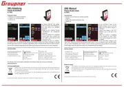
Kontroltype: | Berøring |
Indbygget skærm: | Ja |
Skærm diagonal: | 3 " |
Emballageindhold: | POLARON EX 1400 charger, XH 8S adapter cables, USB cable, DC input cable, 2 x temp. sensors, 2 x charger cables, 2 x crocodile clips, Charger stand, Manual |
DC indgangsspænding: | 11 - 28 V |
Udledningsstrøm: | 0.1 - 10 mA |
Delta peak teknologi: | Ja |
Har du brug for hjælp?
Hvis du har brug for hjælp til Graupner Polaron EX1400 stil et spørgsmål nedenfor, og andre brugere vil svare dig
Batterioplader Graupner Manualer
13 Januar 2025
13 Januar 2025
4 August 2024
27 Juli 2024
8 Juli 2024
Batterioplader Manualer
- Kärcher
- DieHard
- Absima
- Hamron
- Pioneer
- Arctic Cooling
- HQ
- Biltema
- TFA
- KBM
- Lexon
- Technaxx
- Emos
- Jump-N-Carry
- A-solar
Nyeste Batterioplader Manualer
22 September 2025
22 September 2025
21 September 2025
21 September 2025
19 September 2025
19 September 2025
19 September 2025
18 September 2025
18 September 2025
18 September 2025