ECM180D
ECM180D
230V~ 50Hz
0.25-5(80)A Cl. B (Cl.1)
1000
p/kWh
230 V~ 50 Hz
0.
25 -5 (80
)AC l . B (Cl.1)
10 00
p/kW h
320 / MID
0051M 18
z i y
Technical data Technische data Dati tecnici
Data in compliance with EN 50470-1, EN 50470-3, IEC 62053-21 and
IEC62053-23
Gegevens conform EN 50470-1, EN 50470-3, IEC 62053-21 en
IEC62053-23
Dati conformi alle norme EN 50470-1, EN 50470-3, IEC 62053-21 e
IEC62053-23
General characteristics Algemene karakteristieken Caratteristiche generali
Housing DIN 43880 Behuizing DIN 43880 Involucro DIN 43880 DIN 2 0
Mounting EN 60715 Montage EN 60715 Montaggio EN 60715 35 mmDIN rail
Depth Diepte Profondità 60mm
Weight Gewicht Peso 175g
Operating features Bedieningsfuncties Funzionalità operative
Connection to single-phase network - number of wires Verbinding naar eenfasig netwerk - aantal draden Connessione alla rete monofase - numero di li -2
Storage of energy values and
conguration
Internal ash non volatile memory Opslag van energiewaarden en
cong.
Intern ash niet-vluchtig geheugen Memorizzazione dei valori di
energia e congurazione
Memoria interna non volatile -c
Tariff for active and reactive energy Tarief voor reële en reactieve energie Tariffa per energia attiva e reattiva T1 … T2 230V - T1 … T2 M-Bus-
Approval (according to EN 50470-1, EN 50470-3) Goedkeuring (volgens EN 50470-1, EN 50470-3) Omologazione (secondo EN 50470-1, EN 50470-3)
Reference Voltage (Un) (Un)Referentiespanning Tensione di riferimento 230(Un) VAC
Reference Current Referentie stroom Corrente di riferimento 5(Iref) (Iref) (Iref) A
Minimum Current Minimumstroom Corrente minima (Imin) (Imin) (Imin) A 0.25
Maximum Current Maximale stroom Corrente massima 80(Imax) (Imax) (Imax) A
Starting Current Startstroom Corrente di avviamento (Ist) (Ist) (Ist) A 0.015
Reference Frequency Referentie frequentie Frequenza di riferimento 50(fn) (fn) (fn) Hz
Number of phases / number of wires Aantal fasen / aantal draden 1 / 2Numero di fasi / numero di li -
Certied Measures Gecerticeerde maatregelen Misure certicate kWh kWh kWh
Accuracy Nauwkeurigheid Precisione
- Active Energies (accord. to EN 50470-3) - Reële energie (conform EN 50470-3) - Energia attiva (secondo EN 50470-3) classe B / 1
- Active Powers (accord. to IEC 62053-21 and IEC 61557-12) - Reëel vermogen (conform IEC 62053-21 en IEC 61557-12) - Potenza attiva (secondo IEC 62053-21 e IEC 61557-12)
- Reactive Energies (accord. to IEC 62053-23) - Reactive Energieën (conform IEC 62053-23) - Energia reattiva (secondo IEC 62053-23) classe 2
- Reactive Powers (accord. to IEC 62053-21) - Reactief vermogen (conform IEC 62053-21) - Potenza reattiva (secondo IEC 62053-21)
Supply Voltage and Power Consumption Voedingsspanning en Energieverbruik Tensione di alimentazione e potenza assorbita
Operating Supply Voltage range Intervallo tensione di alimentazione 92 … 276Bedrfsspanningbereik V
Maximum Power Consumption (Voltage circuit) Maximaal energieverbruik (Spanningscircuit) Potenza massima assorbita (circuito voltmetrico) ≤2 / ≤1VA / W
Maximum VA burden (Current circuit) @ Maximale VA last (stroom circuit) @ Massimo assorbimento VA (circuito amperometrico) @ ≤1Imax Imax Imax VA
Voltage Input Waveform Meetspanningsvorm Forma d'onda tensione di ingresso AC-
Voltage impedance Impedantie spanningsingang Impedenza circuito voltmetrico 1MΩ
Current impedance Impedantie stroomingang Impedenza circuito amperometrico mΩ ≤20
Overload capability Overbelastingscapaciteit Capacità di sovraccarico
Voltage continuous Spanning doorlopend Tensione continuo 276VAC
temporary (1 s) tdelk (1 s) temporaneo (1 s) VAC 300
Current continuous Stroom doorlopend Corrente continuo 80A
temporary (10 ms) tdelk (10 ms) temporaneo (10 ms) A2400
Measuring Features Meetfuncties Funzioni di misura
Voltage range Spanningsbereik Intervallo di tensione 92 … 276VAC
Current range Stroombereik Intervallo di corrente A0.015 … 80
Frequency range Frequentiebereik Intervallo di frequenza 45 … 65Hz
Measured Quantities Gemeten hoeveelheden Quantità misurate V, A, kWh, kvarh, PF, Hz, kW, kvar-
Display features Display functies Caratteristiche del display
Display type LCD with backlight Display type LCD met achtergrondverlichting Tipo di
visualizzazione
LCD retroilluminato -7.2 +3.2
Active Energy Reële Energie Energia attiva7 digits + 2 decimal digits 7 cfers + 2 decimalen 7 cifre + 2 cifre decimali 0.01 … 9999999.99kWh
Voltage Spanning Tensione3 digits + 2 decimal digits 3 cfers + 2 decimalen 3 cifre + 2 cifre decimali 92.00 … 276.00V
Current Stroom Corrente2 digits + 2 decimal digits 2 cfers + 2 decimalen 2 cifre + 2 cifre decimali 0.00 … 80.00A
Power factor Powerfactor Fattore di potenza1 digit + 3 decimal digits with sign + capac./induc. indic. 1 cfer + 3 decimalen + capaciteit./induc. indic. 1 cifra + 3 cifre decimali con segno + indic. capac. /
indutt.
- -1.000 … 1.000
Frequency Frequentie Frequenza2 digits + 2 decimal digits 2 cfers + 2 decimalen 2 cifre + 2 cifre decimali 45.00 … 65.00Hz
Active Power Reëel vermogen Potenza attiva2 digits + 2 decimal digits with sign 2 cfers + 2 decimalen met teken 2 cifre + 2 cifre decimali con segno 0.00 … 22.08kW
Reactive Power Reactief vermogen Potenza reattiva2 digits + 2 decimal digits with sign 2 cfers + 2 decimalen met teken 2 cifre + 2 cifre decimali con segno 0.00 … 22.08kvar
Running Tariff 1 digit Actueel tarief Tariffa in funzione 1 cifra T1 … T2 230V - T1 … T2 M-Bus1 cfer -
Display refresh period Toon verversingsperiode Frequenza di aggiornamento del display 1s
Optical metrological LED Optische metrologische LED LED metrologico ottico
Front mounted red LED (meter constant) proportional to active imp/
exp Energy
Aan voorzde gemonteerde rode LED (meter
constant)
evenredig met actieve imp /
exp Energie
LED rosso frontale (costante del contatore) proporzionale all'energia imp /
exp. Attiva
p/kWh 1000
Safety Veiligheid Sicurezza
Overvoltage category Overspanningscategorie Categoria di sovratensione 3-
Protective class Beschermingsklasse Classe di protezione IIclasse
AC voltage test (EN 50470-3, 7.2) AC spanningstest (EN 50470-3, 7.2) Test di tensione AC (EN 50470-3, 7.2) kV 4
Degree of pollution Vervuilingsgraad Grado di inquinamento 2-
Operational voltage Nominale spanning Tensione di funzionamento 300V
Impulse voltage test Impulsspanningstest Test di tensione ad impulso 6(Uimp) (Uimp) (Uimp) 1.2/50 μs-kV
Housing material ame resistance Resistenza alla amma del materiale dell'involucroUL 94 Behuizing materiaal vlamwerendheid UL 94 UL 94 classe V0
Safety-sealing between upper and lower housing part Veiligheidsafdichting tussen bovenste en onderste behuizing Sigillo di sicurezza tra la parte superiore e quella inferiore dell'involucro -c
IR Connectable Communication Modules IR-koppelbare communicatiemodules Moduli di comunicazione IR collegabili
For communication modules Voor communicatiemodules Per moduli di comunicazione -c
Embedded M-Bus communication Geïntegreerde communicatie M-Bus Comunicazione incorporata M-Bus
Baud rate Baudrate Velocità Baud 300 … 9600bps
Unit load Busbelasting Carico singolo 1-
Address adjustable Adres Instelbaar Indirizzo regolabile 0 … 250-
Isolation class SELV Isolatieklasse SELV Classe di isolamento SELV -c
Tariff Tarief Tariffa
Tariff 1 Tarief 1 Tariffa 1 -c
Tariff 2 Tarief 2 Tariffa 2 230 ±20%VAC
Input impedance Ingangsimpedantie Impedenza di ingresso 224kΩ
Environmental conditions Milieuomstandigheden Condizioni ambientali
Storage temperature range Opslagtemperatuur Temperatura di stoccaggio °C -25 … +70
Operating temperature range Temperatura di funzionamentoBedrfstemperatuur °C -25 … +55
Mechanical environment Mechanische omgeving Ambiente meccanico M1-
Electromagnetic environment Elektromagnetische omgeving Ambiente elettromagnetico E2-
Installation indoor only Installatie alleen binnen Installazione solo all'interno -c
Altitude (max.) Hoogte (max.) Altitudine (max.) ≤2000m
Humidity yearly average, without condensation Vochtigheid Umidità media annuale, senza condensajaarlks gemiddelde, zonder condensatie -≤75%
on 30 days per year, without condensation op 30 dagen per jaar, zonder condensatie su 30 giorni all'anno, senza condensa -≤95%
IP rating IP rating Grado di protezione IPin built-in condition (front part) in ingebouwde conditie (voorkant) in condizione di incasso (parte frontale) IP51(*)-
terminal block klemblok morsettiera IP20-
(*) For use in accordance with the MID Directive, the energy meter must be installed in a
distribution board/enclosure for modular products with a minimum protection rating IP30
The IP51 ratings apply to the meter parts exposed in front of (outside of) the cover of the
enclosure.
(*) Voor gebruik in overeenstemming met de MID-richtln moet de energiemeter
worden gemonteerd in een verdeelkast voor modulaire producten met een minimale
beschermingsklasse IP30. De IP51 is van toepassing op het gedeelte van de behuizing van
de energiemeter dat door de afdekplaat heen naar buiten steekt..
(*) Per l'utilizzo in conformità alla direttiva MID, il contatore di energia deve essere installato
in un quadro di distribuzione per apparecchi modulari con grado di protezione minimo
IP30. Il grado di protezione IP51 è relativo a parti del contatore esterne al quadro (frontale
dell'apparecchio).
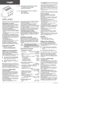
Sealable terminal cover Dimension
Verzegelbare
schroefklemafdekkap Afmetingen
Coprimorsetto sigillabile Dimensione
z
i
y
Wiring diagram
Cable stripping length and terminal screw torque
Aansluitschema
Kabelstriplengte en aandraaimomenten van de
aansluitklemmen
Schema di collegamento
Lunghezza di sguainatura del cavo e coppia della
vite del morsetto
MID certied
MID gecerticeerd
Certicato MID
MID safety sealing
MID-verzegeling
Sigillo di sicurezza MID
6LE005243Ad
1 Hager Electro S.A.S., Boulevard d’Europe, B.P. 3, 67215 OBERNAI CEDEX, France - www.hager.com Hager 09.19 6LE005243AdOCOM 136679