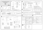
Hikvision DS-PDD12P-EG2 Manual


Læs gratis den danske manual til Hikvision DS-PDD12P-EG2 (4 sider) i kategorien Bevægelsesdetektor. Denne vejledning er vurderet som hjælpsom af 66 personer og har en gennemsnitlig bedømmelse på 3.9 stjerner ud af 33.5 anmeldelser. Har du et spørgsmål om Hikvision DS-PDD12P-EG2, eller vil du spørge andre brugere om produktet?

Side 1/4
Hangzhou Hikvision Digital Technology CO.,Ltd. No.555 Qianmo Road, Binjiang District, Hangzhou 310052, China
E N G L I S H
1
2
34
Specication
1Appearance
1. Lens 2. Pet Mask 3. LED Light Pipe
a. Alarm Resistance: 1K, 2K2, 4K7, 5K6, 6K8
b. Tamper Resistance: 1K, 2K2, 4K7, 5K6
a. Normally Closed: 1. Alarm Control Panel 2. Detector
b. Single End of Line Wiring: 1. Alarm Control Panel 2. Detector
The connection shows the example: Normal: 1K, Alarm: Innite, Tamper: 0K
c. Double End of Line Wiring: 1. Alarm Control Panel 2. Detector
The connection shows the example: Normal: 1K, Alarm: 2K,
Tamper: 0K or innite
Powering On
The 12 m Lens
Installation
Wired Dual Technology Detector
DS-PDD12P-EG2
User Manual
1 2 3 4 5
6
7
4. Lens Holder
5. PCB 6. Nut 7. Casing Screw
5The Printed Circuit Board (PCB)
1. PIR Sensor
4. Tamper Resistor Headers 5. Terminals
7. Tamper Spring
9. Sensitivity Settings
8. LED ON/OFF
6. Alarm Resistor Headers
AUTO PET
LED ON LED OFF
99 g
(3.5 oz)
45.5 mm
65.7 mm
103.8 mm
a. Detection Range: 85.9°, 52 zones, 4 planes
b. Mouting Height:
Mounting height range from 1.8 m to 2.4 m.
The recommended mounting height is 2.2 m.
c. Microwave Range Control:
Max: 11 to 12 m Medium: 2 to 11 m Min: 0 to 2 m
=
=
1K
ALARMTAMPER
6K8
5K6
4K7
2K2
1K
5K6
4K7
2K2
1K
+- ALARMTAMPER
EOLEOL
ALARMTAMPER
6K8
5K6
4K7
2K2
1K
5K6
4K7
2K2
1K
+- ALARMTAMPER
EOLEOL
ALARMTAMPER
6K8
5K6
4K7
2K2
1K
5K6
4K7
2K2
1K
+- ALARMTAMPER
EOLEOL
ALARMAMPER
6K8
5K6
4K7
2K2
1K
5K6
4K7
2K2
1K
+- ALARMTAMPER
EOL
1K
ZONE2
COM
ZONE1
COM
+-
ALARMTAMPER +-
6K8
5K6
4K7
2K2
1K
5K6
4K7
2K2
1K
ALARMTAMPER
EOLEOL
ALARMTAMPER +-
6K8
5K6
4K7
2K2
1K
5K6
4K7
2k2
1K
ALARMTAMPER
EOLEOL
ZONE2
COM
ZONE1
COM
+-
ALARMTAMPER +-
6K8
5K6
4K7
2K2
1K
5K6
4K7
2K2
1K
ALARMTAMPER
EOLEOL
ZONE2
COM
ZONE1
COM
+-
a
1
2
a
b
Screw Model: PA_3.5 ×25 (4 screws)
a. Ceiling Bracket Fitting
b. Wall Bracket Fitting
Note: Brackets are optional.
Resistor Wiring
Connection Type
The detector has two method for resistor wiring:
(1) Using headers to select the End of Line resistance (Control panel
dependent) on the ALARM/TAMPER header pins.
(2) Select an resistance (Control panel dependent), and add the resistor to
ALARM/TAMPER wiring ports of the detector.
Note: If EOL (End of Line) wiring is not used, leave the headers OFF. If the
headers and the header pins does not match, do not force the header, please
select the method 2 to wire the resistor. Method 1 and method 2 should not
be used on the ALARM/TAMPER at the same time.
After powering on, the indicator ashes rapidly. Once the detector self test
is completed, the LED indicator will go out until the detector detects
movement.
b
2
3
4
5
6
5a
b
1
2
c1
2
6
UD20003B-G
1K, 2K2,
4K7, 5K6, 6K8
6
1K,2K2,
4K7,5K6
4
AUTO
PET
LED ON
LED OFF
AND
OR
1
2
3
5
7
8
9
10
2. MW Range Control 3. Microwave Module
10. AND/OR Mode AUTO OR
12
3
4
85.9°
Detection Range
52 zones
4 planes
10m 12m1m 2m 4m 6m 8m
10m 12m1m
2.4m
2m 4m 6m 8m
10m
12m
1m
2m
4m
6m
8m
Microwave Range Control
Max: 11 to 12 m
Medium: 2 to 11 m
Min: 0 to 2 m
NOT READY READY
Optional wall & ceiling accessoryBracket
99 gWeight
103.8 mm × 65.7 mm × 45.5 mmDimension (H × W × D)
1.8 to 2.4mInstallation height
10% to 90%Operating humidity
-20 °C to 60 °C (-4 °F to 140 °F)Storage temperature
-10 °C to 55 °C (14 °F to 131 °F)
-10 °C to 40 °C (14 °F to 104 °F) Certied
Operating temperature
17mA quiescent and maximum at 12V DCCurrent consumption
9 to 16 VDC (standard: 12 VDC)Power supply
< 30 kgPet immunity
AND = PIR + MW
OR = PIR / MW (shouldn’t be used with pets)
AND/OR mode
Potentiometer adjustmentMicrowave range
24Ghz (24.075Ghz to 24.175Ghz)Microwave frequency
Green(PIR), Orange(microwave), Blue(alarm)LED indicators
FrontTamper protection
YesCreep zone protection
YesSealed optics
Digital microprocessor basedTechnology
Yes
Digital temperature compensation Yes
Onboard EOL
YesAuto sensitivity
Auto, PetSensitivity
0.3 ~ 2 m/sDetection speed
12m, 85.9°Detection range
1
2
1
2
3
Notes: In Brazil the device only operates in 24.25 GHz.
Intrusion detector - Dual Technology detector
EN 50131-2-4:2020, Security Grade2, Environment Class II
Tested by TÜV Rheinland
2Installation
Modèle de vis : PA_3.5 × 25 (4 vis)
a. Installation du support de plafond b. Installation du support mural
Remarque : les supports sont en option.
3Lobjectif 15 m
a. Portée de détection : 85,9°, 52 zones, 4 plans
b. Hauteur d’installation : Plage de hauteurs d’installation de 1,8 à 2,4 m. La hauteur d’installation recommandée est
de 2,2 m.
c. Contrôle de la portée micro-ondes : Max. : 11 à 12 m Moyenne : 2 à 11 m Min. : 0 à 2 m
4Câblage des résistances
Le détecteur ore deux méthodes de câblage des résistances :
(1) Utilisez les embases pour sélectionner la résistance de n de ligne (en fonction du panneau de commande) sur les
broches d’embases ALARME/ANTI-SABOTAGE ;
(2) Sélectionnez une résistance (en fonction du panneau de contrôle), et ajoutez la résistance aux ports
ALARME/ANTI-SABOTAGE du détecteur.
Remarque : si le câblage EOL (n de ligne) n’est pas utilisé, laisser les embases éteintes. Si les embases et les broches
d’embases ne correspondent pas, ne forcez pas l’embase ; optez pour la 2e méthode de câblage de la résistance. La
1re et la 2e méthodes ne doivent pas être utilisées en même temps sur l’ALARME/ANTI-SABOTAGE.
a. Résistance d’alarme : 1K, 2K2, 4K7, 5K6, 6K8
b. Résistance anti-sabotage : 1K, 2K2, 4K7, 5K6
5Type de connexion
a. Normalement fermé: 1. Panneau de contrôle d’alarme 2. Détecteur
b. Câblage d’une seule extrémité de ligne : 1. Panneau de contrôle d’alarme 2. Détecteur
La connexion montre l’exemple : Normal : 1K, alarme : innie, anti-sabotage : 0K
c. Câblage d’une double extrémité de ligne : 1. Panneau de contrôle d’alarme 2. Détecteur
La connexion montre l’exemple : Normal : 1K, alarme : 2K, anti-sabotage : 0K ou inni
6Mise sous tension
Une fois allumé, le voyant clignote rapidement. À la n de l’autodiagnostic du détecteur, l’indicateur LED s’éteint
jusqu’à ce qu’un mouvement soit détecté.
1
5
F R A N Ç A I S
Apparence
1. Objectif 2. Cache de protection contre les animaux 3. Conducteur de lumière LED 4. Porte-objectif
5. PCB 6. Écrou 7. Vis du boîtier
Circuit imprimé (PCB)
1. Capteur PIR 2. Contrôle de la portée micro-ondes 3. Module Micro-ondes
5. Bornes4. Embases de résistance anti-sabotage
6. Embases de résistance d'alarme
Spécication
7. Ressort anti-sabotage
9. Paramètres de sensibilité
8. LED ALLUMÉE/ÉTEINTE
AUTO ANIMAUX
LED ALLUMÉE LED ÉTEINTE
10. Mode ET/OU AUTO OU
Portée de détection
Vitesse de détection
Sensibilité
Sensibilité auto
EOL embarqué
Compensation numérique de la
température
Technologie
Optiques scellées
Protection de zone au ras du mur
Protection anti-sabotage
Indicateurs LED
Fréquence des micro-ondes
12 m, 85,9°
De 0,3 m/s à 2 m/s
Auto, Animaux
Oui
Oui
Oui
Repose sur un microprocesseur numérique
Oui
Oui
Panneau avant
Vert (PIR), orange (micro-ondes), bleu (alarme)
24 GHz (24,075 GHz à24,175 GHz)
Portée des micro-ondes Réglage du potentiomètre
Mode ET/OU
Filtre à animaux de compagnie
Alimentation électrique
Consommation de courant
Température de fonctionnement
Température de stockage
Humidité de fonctionnement
Hauteur d’installation
Dimension (L x l x h)
Poids
Support
ET = PIR + MW
OU = PIR / MW (ne doit pas être utilisé avec les
animaux de compagnie)
< 30 kg
9 à 16 V CC (standard : 12 V CC)
17 mA au repos et maximale à 12 V CC
De -10 °C à 55 °C
-10 à 40 °C certié
De -20 °C à 60 °C
De 10 à 90 %
De 1,8 à 2,4 m
103,8 mm × 65,7 mm× 45,5 mm
99 g
Accessoire mural et plafond facultatif
2Installation
Schraubenausführung: PA_3,5 × 25 (4 Schrauben)
a. Deckenhalterung b. Wandhalterung
Hinweis: Die Halterungen sind optional.
3Das 15-m-Objektiv
a. Erkennungsbereich: 85,9°, 52 Zonen, 4 Ebenen
b. Befestigungshöhe: Montagehöhenbereich von 1,8 m bis 2,4 m. Die empfohlene Montagehöhe ist 2,2 m.
c. Mikrowellen-Reichweitensteuerung: Max.: 11 bis 12 m Mittel: 2 bis 11 m Min.: 0 bis 2 m
4Widerstandsverdrahtung
Der Melder verfügt über zwei Methoden zur Widerstandsverdrahtung:
(1) Verwendung von Jumpern, um den Leitungs-Abschlusswiderstand (abhängig von der Zentrale) auf der
ALARM/SABOTAGE-Stiftleiste zu wählen.
(2) Auswahl eines Widerstands (abhängig von der Zentrale) und Anschluss an die ALARM/SABOTAGE-Anschlüsse des
Melders.
Hinweis: Wenn keine Leitungsabschlussverdrahtung (EOL) verwendet wird, benutzen Sie keine Jumper. Wenn die
Jumper nicht auf die Stiftleiste passen, versuchen Sie nicht, sie mit Gewalt aufzustecken, sondern wählen Sie
Methode 2, um den Widerstand zu verdrahten. Methode 1 und 2 dürfen nicht gleichzeitig auf den
ALARM/SABOTAGE-Stiftleisten verwendet werden.
a. Alarmwiderstand: 1K, 2K2, 4K7, 5K6, 6K8
b. Sabotagewiderstand: 1K, 2K2, 4K7, 5K6
5Anschlussart
a. Ruhekontakt: 1. Alarmzentrale 2. Melder
b. Einzel-Leitungsabschlussverdrahtung: 1. Alarmzentrale 2. Melder
Der Anschluss wird im Beispiel dargestellt: Normal: 1K, Alarm: Unendlich, Sabotage: 0K
c. Doppel-Leitungsabschlussverdrahtung: 1. Alarmzentrale 2. Melder
Der Anschluss wird im Beispiel dargestellt: Normal: 1K, Alarm: 2K, Sabotage: 0K oder unbegrenzt
6Einschalten
Nach dem Einschalten blinkt die LED schnell. Sobald der Selbsttest des Melders abgeschlossen ist, erlischt die
LED-Anzeige, bis der Melder eine Bewegung erkennt.
1
5
D E U T S C H
Aufbau
1. Objektiv 2. Haustier-Maske 3. LED-Lichtrohr 4. Objektivhalter
5. Leiterplatte 6. Mutter 7. Gehäuseschraube
Gedruckte Leiterplatte (PCB)
1. PIR-Sensor 2. MW-Reichweitensteuerung 3. Mikrowellenmodul
5. Anschlussklemmen4. Stiftleisten des Sabotagewiderstands
6. Stiftleisten des Alarmwiderstands
Technische Daten
7. SABOTAGE-Feder
9. Empndlichkeitseinstellungen
8. LED AN/AUS
AUTO HAUSTIER
LED AUS LED AN
10. UND/ODER-Modus AUTO ODER
Erkennungsbereich
Erfassungsgeschwindigkeit
Empndlichkeit
Auto-Empndlichkeit
Onboard-EOL
Digitaler
Temperaturkompensation
Technologie
Versiegelte Optik
Kriechzonenschutz
Sabotageschutz
LED-Anzeigen
Mikrowellenfrequenz
12 m, 85,9°
0,3 bis 2 m/s
Auto, Haustier
Ja
Ja
Ja
Mit digitalem Mikroprozessor
Ja
Ja
Vorne
Grün (PIR), Orange (Mikrowelle), Blau (Alarm)
24 GHz (24,075 GHz bis 24,175 GHz)
Mikrowellenreichweite Potentiometer-Einstellung
UND/ODER-Modus
Haustier-Unterdrückung
Spannungsversorgung
Stromaufnahme
Betriebstemperatur
Lagertemperatur
Betriebsfeuchtigkeit
Montagehöhe
Maße (H x B x T)
Gewicht
Halterung
UND = PIR + MW
ODER = PIR/MW (nicht mit Haustieren verwenden)
< 30 kg
9 bis 16 V DC (Standard: 12 V DC)
17 mA Ruhestrom und Maximumbei 12 V DC
-10 °C bis 55 °C
-10 °C bis +40 °Czertiziert
-20 °C bis +60 °C
10 % bis 90 %
1,8 bis 2,4 m
103,8 mm x 65,7 mmx 45,5 mm
99 g
Optionales Zubehör für Wand- und Deckenmontage
2Installazione
Tipo di vite: PA_3.5 ×25 (4 viti)
a. Montaggio con staa a sotto b. Montaggio con staa a parete
Nota: le stae sono opzionali.
3Obiettivo 15 m
a. Area di copertura: 85.9°, 52 zone, 4 piani
b. Altezza di montaggio: Altezza di montaggio compresa tra 1,8 m e 2,4 m. Si consiglia di montare a un'altezza di 2,2 m.
c. Controllo portata microonde: Max: 11-12 m Media: 2-11 m Min: 0-2 m
4Cablaggio della resistenza
Il rilevatore supporta due metodi di collegamento per la resistenza:
(1) Utilizzare i ponticelli per selezionare la resistenza di ne linea (in base al pannello di controllo) sui terminali
ALARM/MANOMISSIONE.
(2) Selezionare una resistenza (in base al pannello di controllo) e aggiungere la resistenza alle porte di cablaggio
ALARM/MANOMISSIONE del rilevatore.
Nota: se non si utilizza il cablaggio di ne linea (EOL), lasciare i ponticelli DISINSERITI. Se i ponticelli e gli alloggiamenti
non corrispondono, non forzare i ponticelli e scegliere il secondo metodo di collegamento della resistenza. Il primo e il
secondo metodo non devono essere utilizzati contemporaneamente.
a. Resistenza allarme: 1K, 2K2, 4K7, 5K6, 6K8
b. Resistenza antimanomissione: 1K, 2K2, 4K7, 5K6
5Tipo di collegamento
a. Normalmente chiuso: 1. Pannello di controllo allarme 2. Rilevatore
b. Cablaggio di ne linea singolo: 1. Pannello di controllo allarme 2. Rilevatore
Esempio di collegamento: Normale: 1K, Allarme: Innito, Antimanomissione: 0K
c. Cablaggio di ne linea doppio: 1. Pannello di controllo allarme 2. Rilevatore
Esempio di collegamento: Normale: 1K, Allarme: 2K, Antimanomissione: 0K o innito
6Accensione
Quando si accende il rilevatore, l'indicatore lampeggerà rapidamente. Al termine dei test autodiagnostici, l'indicatore
LED si spegne nché viene rilevato un movimento.
1
5
I T A L I A N O
Aspetto
1. Obiettivo 2. Mascheramento animali (PET) 3. Illuminazione tubolare a LED 4. Porta obiettivo
5. PCB 6. Dado 7. Vite custodia
Circuito stampato (PCB)
1. Sensore PIR 2. Controllo portata microonde 3. Modulo microonde
5. Terminali4. Jumper resistenza antimanomissione
6. Jumper resistenza allarme
Speciche
7. Molla antimanomissione
9. Impostazioni di sensibilità
8. LED ACCESO/SPENTO
AUTO PET
LED ACCESO LED SPENTO
10. Modalità E/O AUTO O
Area di copertura
Velocità di rilevamento
Sensibilità
Sensibilità automatica
EOL integrata
Compensazione digitale della
temperatura
Tecnologia
Componenti ottici sigillati
Protezione zona antistrisciamento
Protezione antimanomissione
Indicatori LED
Frequenza microonde
12 m, 85,9°
0,3-2 m/s
Auto, Animale domestico
Con microprocessore digitale
Parte anteriore
Verde (PIR), arancione (microonde), blu (allarme)
24 Ghz (da 24.075 Ghz a24.175 Ghz)
Gamma microonde Regolazione potenziometro
Modalità E/O
Immunità per gli animali domestici
Alimentazione
Assorbimento
Temperatura operativa
Temperatura di conservazione
Umidità operativa
Altezza di installazione
Dimensioni (A × L × P)
Peso
Staa
E = PIR + MW
O = PIR / MW (da non usare con animali domestici)
<30 kg
9-16 VCC (standard: 12 VCC)
17 mA quiescente; max 12 VCC
Da -10 °C a 55 °C (da 14 °F a 131 °F)
Da -10 °C a 40 °C (da 14 °F a 104 °F) certicata
Da -20 °C a 60 °C (da -4 °F a 140 °F)
Da 10% a 90%
1,8-2,4 m
103,8 mm × 65,7 mm× 45,5 mm
99 g
Accessorio da parete e sotto opzionale
2Instalação
Modelo do parafuso: PA_3.5 × 25 (4 parafusos)
a. Instalação em suporte de teto b. Instalação em suporte de parede
Observação: os suportes são opcionais.
3Lente de 15 m
a. Faixa de detecção: 85,9°, 52 zonas, 4 planos
b. Altura de montagem: Altura de montagem de 1,8 a 2,4 m. A altura recomendada é de 2, 2 m.
c. Controle da faixa de micro-ondas: Máx.: 11 a 12 m Média: 2 a 11 m Mín.: 0 a 2 m
4Conexão do resistor
O detector tem dois métodos para a conexão do resistor:
(1) Use jumpers para selecionar a resistência de m de linha (conforme o painel de controle) nos cabeçotes dos pinos
de ALARME/VIOLAÇÃO.
(2) Selecione uma resistência (conforme o painel de controle) e adicione o resistor às portas de conexão de
ALARME/VIOLAÇÃO do detector.
Observação: Se a conexão EOL (m de linha) não for usada, deixe os cabeçotes desligados. Se os jumpers e os
cabeçotes dos pinos não forem compatíveis, não force o jumper. Selecione o método 2 para conectar o resistor. Os
métodos 1 e 2 não devem ser usados ao mesmo tempo para ALARME/VIOLAÇÃO.
a. Resistência do alarme: 1K, 2K2, 4K7, 5K6, 6K8
b. Resistência de antiviolação: 1K, 2K2, 4K7, 5K6
5Tipo de conexão
a. Normalmente fechada: 1. Painel de controle de alarme 2. Detector
b. Fiação de m de linha único: 1. Painel de controle de alarme 2. Detector
Conexão mostrada no exemplo: Normal: 1K, Alarme: innito, Violação: 0K
c. Fiação de m de linha duplo: 1. Painel de controle de alarme 2. Detector
Conexão mostrada no exemplo: Normal: 1K, Alarme: 2K, Violação: 0K ou innito
6Ligar
Após ligado, o indicador piscará rapidamente. Quando o autoteste do detector estiver concluído, o indicador de LED
apagará até que o detector detecte um movimento.
1
5
P O R T U G U Ê S
Apresentação
1. Lente 2. Máscara de animais 3. Tubo de luz de LED 4. Suporte da lente
5. PCB 6. Porca 7. Parafuso do invólucro
Placa de circuito impresso (PCB)
1. Sensor PIR 2. Controle da faixa de micro-ondas 3. Módulo de micro-ondas
5. Terminais4. Cabeçotes do resistor antiviolação
6. Cabeçotes do resistor de alarme
Especicações
7. Mola antiviolação
9. Congurações de sensibilidade
8. LED LIG/DESLIG
Automática Pet
LED ligado LED desligado
10. Modo E/OU Automática OU
Alcance de detecção
Velocidade de detecção
Sensibilidade
Sensibilidade automática
EOL integrado
Compensação de temperatura
digital
Tecnologia
Óptica selada
Proteção da zona de rastejamento
Proteção antiviolação
Indicadores LED
Frequência de micro-ondas
12 m, 85,9°
0,3 a 2 m/s
Automática, pet
Sim
Sim
Sim
Baseado em microprocessador digital
Sim
Sim
Parte dianteira
Verde (PIR), Laranja (micro-ondas), Azul (alarme)
24 Ghz (24,075 Ghz a24,175 Ghz)
Faixa de micro-ondas Ajuste do potenciômetro
Modo E/OU
Imunidade a pet
Fonte de alimentação
Consumo de corrente
Temperatura de operação
Temperatura de armazenamento
Umidade de operação
Altura de instalação
Dimensões (A × L × P)
Peso
Suporte
E = PIR + MW
OU = PIR / MW (não deve ser usado com pets)
< 30 kg
9 a 16 VCC (padrão: 12 VCC)
17 mA em inatividade e máxima em 12 VCC
-10 °C a 55 °C(14 °F a 131 °F)
-10 °C a 40 °C(14 °F a 104 °F) certicada
-20 °C a 60 °C(-4 °F a 140 °F)
10% a 90%
1,8 m a 2,4 m
103,8 mm × 65,7 mm× 45,5 mm
99 g
Acessório opcional de parede e teto
2Установка
Модель на винтах: PA_3,5 ×25 (4 винта)
a. Кронштейн для монтажа на потолок b. Кронштейн для монтажа на стену
Примечание. Крепления заказываются отдельно.
3Линза 15 м
a. Диапазон обнаружения: 85,9°, 52 зоны, 4 плоскости
b. Высота монтажа: Высота монтажа выбирается в диапазоне от 1,8 м до 2,4 м. Рекомендуемая высота
установки составляет 2,2 м.
c. Диапазон микроволнового датчика: Макс.: 11-12 м Средний: 2–11 м Мин: 0–2 м
4Разводка для подключения резистора
Имеется два способа подключения резистора:
(1) С помощью перемычек выберите резистор в конце линии (зависит от панели управления), замыкая
контакты в группе "СИГНАЛИЗАЦИЯ/ЗАЩИТА ОТ ВЗЛОМА".
(2) Выберите резистор (зависит от панели управления) и подключите его к портам разводки датчика
"СИГНАЛИЗАЦИЯ/ЗАЩИТА ОТ ВЗЛОМА".
Примечание. Если резистор в конце линии не используется, отставьте перемычки в положении ВЫКЛ. Если
перемычка не подходит к контактам, не прилагайте усилие к перемычке и выберите способ 2 для
подключения резистора. Способ 1 и способ 2 не должны применяться в группе "СИГНАЛИЗАЦИЯ/ЗАЩИТА ОТ
ВЗЛОМА" одновременно.
a. Сопротивление сигнализации: 1 кОм, 2,2 кОм, 4,7 кОм, 5,6 кОм, 6,8 кОм
b. Сопротивление защиты от взлома: 1 кОм, 2,2 кОм, 4,7 кОм, 5,6 кОм
5Тип соединения
a. Нормально замкнуто: 1. Панель управления сигнализацией 2. Датчик
b. Линия с одним концевым резистором: 1. Панель управления сигнализацией 2. Датчик
Показан пример соединения: Нормальный режим: 1 кОм, сигнализация: бесконечное, взлом: 0 кОм
b. Линия с двумя концевыми резисторами: 1. Панель управления сигнализацией 2. Датчик
Показан пример соединения: Нормальный режим: 1 кОм, сигнализация: 2 кОм, взлом: 0 кОм или бесконечное
6Включение
После подключения питания индикатор начинает часто мигать. После завершения самопроверки детектора
светодиодный индикатор выключается, пока датчик не обнаружит движение.
1
5
Р У С С К И Й
Внешний вид
1. Объективы 2. Маска питомцев 3. Светодиодная трубка 4. Держатель линзы
5. Печатная плата 6. Гайка 7. Винт корпуса
Печатная плата
1. Датчик PIR 2. Регулятор дальности действия микроволнового датчика 3. Микроволновый модуль (MW)
5. Разъемы4. Головки резисторов противовзломной защиты
6. Головки резисторов сигнализации
Технические данные
7. Пружина противовзломной защиты
9. Параметры чувствительности
8. Светодиод ВКЛ./ВЫКЛ.
Авто Питомец
Светодиод ВКЛ. Светодиод ВЫКЛ.
10. Режим И/ИЛИ Авто ИЛИ
Радиус действия
Скорость обнаружения
Уровень чувствительности
Автоматическая настройка
чувствительности
Концевой резистор на плате
Цифровая компенсация
температуры
Технология
Герметичная оптика
Защита нижней зоны
Защита от взлома
Светодиодные индикаторы
Частота микроволного излучения
12 м, 85,9°
0,3–2 м/с
Автоматический, защита от срабатывания на животных
Да
Да
Да
На базе цифрового микропроцессора
Да
Да
Передняя панель
Зеленый (инфракрасный), оранжевый (микроволновый),
синий (тревога)
24 ГГц (от 24,075 до 24,175 ГГц)
Диапазон микроволнового
датчика Регулировка потенциометра
Режим И/ИЛИ
Защита от срабатывания на
животных
Источник питания
Энергопотребление
Рабочая температура
Температура при хранении
Рабочая влажность
Высота монтажа
Размеры (В × Ш × Г)
Вес
Кронштейн
И = PIR (инфракрасный) + MW (микроволновый)
ИЛИ = PIR/MW тот режим не должен использоваться
при наличии домашних животных)
< 30 кг
От 9 до 16 В пост. тока (стандартное значение: 12 В
пост. тока)
17 мА в режиме ожидания, максимально при 12 В
пост. тока
от -10 °C до 55 °C
от -10 °C до 40 °C (сертифицировано)
от -20 °C до 60 °C
10–90%
от 1,8 до 2,4 м
103,8 х 65,7 х 45,5 мм
99 г.
Дополнительные принадлежности для крепления на
стене и потолке
2Installatie
Schroefmodel: PA_3.5 ×25 (4 schroeven)
a. Montage plafondsteun b. Montage wandsteun
Opmerking: Beugels zijn optioneel.
3De 15 m Lens
a. Detectiebereik: 85,9°, 52 zones, 4 vlakken
b. Montagehoogte: Montagehoogte tussen 1,8 m en 2,4 m. De aanbevolen montagehoogte is 2,2 m.
c. Microgolfbereikregeling: Max.: 11 to 12 m Midden: 2 to 11 m Min.: 0 to 2 m
4Bedrading van weerstand
De weerstanden van de detector kunnen op twee manieren bedraad worden:
(1) Door gebruik van headers om de End of Line-weerstand (afhankelijk van het bedieningspaneel) te selecteren op
de ALARM/SABOTAGE-headerpennen.
(2) Selecteer een weerstand (afhankelijk van het bedieningspaneel) en voeg de weerstand toe aan de
ALARM/SABOTAGE-bedradingspoorten van de detector.
Opmerking: Als er geen End of Line-bedrading (EOL) wordt gebruikt, laat u de headers UIT. Als de headers en de
headerpennen niet overeenkomen, forceer de header dan niet, maar gebruik methode 2 om de weerstand te
bedraden. Methode 1 en methode 2 mogen niet tegelijkertijd op de ALARM/SABOTAGE worden gebruikt.
a. Alarmweerstand: 1K, 2K2, 4K7, 5K6, 6K8
b. Sabotageweerstand: 1K, 2K2, 4K7, 5K6
5Verbindingstype
a. Normaal gesloten: 1. Bedieningspaneel alarm 2. Detector
b. Enkele End of Line-bedrading: 1. Bedieningspaneel alarm 2. Detector
De verbinding toont het voorbeeld: Normaal: 1K, Alarm: Oneindig, Sabotage: 0K
c. Dubbele End of Line-bedrading: 1. Bedieningspaneel alarm 2. Detector
De verbinding toont het voorbeeld: Normaal: 1K, Alarm: 2K, Sabotage: 0K of oneindig
6Inschakelen
Na het opstarten knippert de indicator snel. Zodra de zelftest van de detector is voltooid, gaat de led-indicator uit
totdat de detector beweging detecteert.
1
5
N E D E R L A N D S
Uiterlijk
1. Lens 2. Petmasker 3. Pijp met led-licht 4. Lenshouder
5. PCB 6. Moer 7. Behuizingsschroef
De printplaat (PCB)
1. PIR-sensor 2. MW-bereikregeling 3. Microgolfmodule
5. Aansluitingen4. Sabotagebestendige koppen
6. Alarmbestendige koppen
Specicatie
7. Sabotageveer
9. Gevoeligheidsinstellingen
8. LED AAN/UIT
AUTO PET
LED AAN LED UIT
10. EN/OF-modus AUTO OF
Detectiebereik
Detectiesnelheid
Gevoeligheid
Automatische gevoeligheid
Interne EOL
Digitale
temperatuurcompensatie
Technologie
Afgedichte optica
Kruipzonebescherming
Sabotagebescherming
Led-indicators
Microgolrequentie
12 m, 85,9°
0,3 - 2 m/s
Auto, Pet
Ja
Ja
Ja
Op basis van digitale microprocessor
Ja
Ja
Voorzijde
Groen (PIR), Oranje (microgolf), Blauw(alarm)
24 GHz (24,075 GHz tot24,175 GHz)
Microgolfbereik Afstelling potentiometer
EN/OF-modus
Immuniteit voor huisdieren
Stroomvoorziening
Stroomverbruik
Bedrijfstemperatuur
Opslagtemperatuur
Bedrijfsvochtigheid
Installatiehoogte
Afmetingen (H × B × D)
Gewicht
Beugel
EN = PIR + MW
OF = PIR / MW (niet gebruiken met huisdieren)
< 30 kg
9 tot 16 VDC (standaard: 12 VDC)
17 mA in rust en maximaal bij 12 V gelijkstroom
-10 °C tot 55 °C
-10 °C tot + 40°C (14 °F tot 104 °F)
-20 °C tot 60 °C
10% tot 90%
1,8 tot 2,4 m
103,8 mm × 65,7 mm× 45,5 mm
99 g
Optioneel muur- en plafondaccessoire
2Kurulum
Vida Modeli: PA_3,5 ×25 (4 vida)
a. Tavan Braketi Tertibatı b. Duvar Braketi Tertibatı
Not: Braketler opsiyoneldir.
315 m Lens
a. Algılama Menzili: 85,9°, 52 bölge, 4 düzlem
b. Montaj Yüksekliği: Montaj yüksekliği 1,8 m ila 2,4 m arasındadır. Önerilen montaj yüksekliği 2,2 m'dir.
c. Mikrodalga Mesafe Kontrolü: Maks.: 11 ila 12 m Orta: 2 ila 11 m Min: 0 ila 2 m
4Rezistans Kabloları
Dedektör, rezistans kabloları için iki yönteme sahiptir:
(1) ALARM/KURCALAMA başlık pimlerinde (Kontrol paneline bağlı) Hat Sonu direncini seçmek için başlıkların
kullanılması.
(2) Bir direnç (Kontrol paneline bağlı) seçin ve rezistansı dedektördeki ALARM/KURCALAMA kablo portlarına bağlayın.
Not: EOL (Hat Sonu) kabloları kullanılmıyorsa başlıkları KAPALI bırakın. Başlıklar ve başlık pimleri eşleşmiyorsa başlığı
zorlamayın. Lütfen rezistansı kablolamak için 2. yöntemi seçin. Yöntem 1 ve yöntem 2, ALARM/KURCALAMA’da aynı
anda kullanılmamalıdır.
a. Alarm Direnci: 1K, 2K2, 4K7, 5K6, 6K8
b. Kurcalama Direnci: 1K, 2K2, 4K7, 5K6
5Bağlantı Tipi
a. Normal Kapatıldı: 1. Alarm Kontrol Paneli 2. Dedektör
b. Tek Hat Sonu Kablolaması: 1. Alarm Kontrol Paneli 2. Dedektör
Bağlantı örneği gösterir: Normal: 1K, Alarm: Sonsuz, Kurcalama: 0K
c. Çift Hat Sonu Kablolaması: 1. Alarm Kontrol Paneli 2. Dedektör
Bağlantı örneği gösterir: Normal: 1K, Alarm: 2K, Kurcalama: 0K veya sonsuz
6Gücü Açma
Açtıktan sonra gösterge hızlı bir şekilde yanıp söner. Dedektör otomatik testi tamamlandıktan sonra dedektör hareket
algılayana kadar LED göstergesi söner.
1
5
T Ü R K Ç E
Görünüm
1. Lens 2. Evcil Hayvan Maskesi 3. LED Işıklı Boru 4. Lens Tutucusu
5. PCB 6. Somun 7. Mahfaza Vidası
Basılı Devre Kartı (PCB)
1. PIR Sensörü 2. MW Mesafe Kontrolü 3. Mikrodalga Modülü
5. Terminaller4. Kurcalama Rezistans Başlıkları
6. Alarm Rezistans Başlıkları
Özellikler
7. Kurcalama Yayı
9. Hassasiyet Ayarları
8. LED AÇIK/KAPALI
OTO PET
LED AÇIK LED KAPALI
10. VE/VEYA Modu OTO VEYA
Algılama aralığı
Algılama hızı
Hassasiyet
Oto. hassasiyet
Dahili EOL
Dijital sıcaklık telasi
Teknoloji
Mühürlü optikler
Sürünme bölgesi koruması
Kurcalama koruması
LED göstergeleri
Mikrodalga frekansı
12 m, 85,9°
0,3 ~ 2 m/s
Otomatik, Evcil Hayvan
Evet
Evet
Evet
Dijital mikroişlemci tabanlı
Evet
Evet
Ön
Yeşil (PIR), Turuncu (mikrodalga), Mavi (alarm)
24Ghz (24.075Ghz ila 24.175Ghz)
Mikrodalga aralığı Potansiyometre ayarı
VE/VEYA modu
Evcil hayvanlardan etkilenmeme
Güç kaynağı
Akım tüketimi
Çalışma sıcaklığı
Depolama sıcaklığı
Çalışma nemi
Montaj yüksekliği
Boyut (Y × G × D)
Ağırlık
Braket
VE = PIR + MW
VEYA = PIR / MW (evcil hayvanlarla kullanılmamalı)
< 30 kg
9 ila 16 VDC (standart:12 VDC)
17 mA sessiz ve 12 V DC'de maksimum
-10 °C ila 55 °C (14 °F ila 131 °F)
-10 °C ila 40 °C (14 °F ila 104 °F) Sertika
-20 °C ila 60 °C (-4 °F ila 140 °F)
%10 ila %90
1,8 ila 2,4 m
103,8 mm x 65,7 mmx 45,5 mm
99 g
Opsiyonel duvar ve tavan aksesuarı
2Instalación
Modelo de tornillo: PA_3,5 × 25 (4 tornillos)
a. Accesorio de soporte de techo b. Accesorio de soporte de pared
Nota: Los soportes son opcionales.
3Lente de 15 m
a. Campo de detección: 85,9°, 52 zonas, 4 planos
b. Altura de montaje: El intervalo de la altura de montaje va desde 1,8 m hasta 2,4 m, siendo la altura recomendada
de 2,2 m.
c. Control de alcance de microondas: Máx.: 11 a 12 m Medio: 2 a 11 m Mín.: 0 a 2 m
4Cableado de la resistencia
El detector es compatible con dos métodos para el cableado de la resistencia:
(1) Use los conectores para seleccionar la resistencia de n línea (en función del panel de control) sobre los pines de
los conectores de ALARMA/MANIPULACIÓN.
(2) Seleccione una resistencia (en función del panel de control) y añádala a los puertos de cableado de
ALARMA/MANIPULACIÓN del detector.
Nota: Si no usa un cableado de n de línea, no use los conectores. Si los conectores y los pines de los conectores no
son compatibles, no fuerce los conectores y seleccione el método 2 para cablear la resistencia. No utilice el método
1 y el método 2 al mismo tiempo para la ALARMA/MANIPULACIÓN.
a. Resistencia de la alarma: 1K, 2K2, 4K7, 5K6, 6K8
b. Resistencia de manipulación: 1K, 2K2, 4K7, 5K6
5Tipo de conexión
a. Normalmente Cerrado: 1. Panel de control de alarmas 2. Detector
b. Cableado de Fin de línea único: 1. Panel de control de alarmas 2. Detector
Conexiones mostradas en el ejemplo: Normal: 1K, Alarma: Innita, Manipulación: 0K
c. Cableado de Fin de línea doble: 1. Panel de control de alarmas 2. Detector
Conexiones mostradas en el ejemplo: Normal: 1K, Alarma: 2K, Manipulación: 0K o innita
6Encendiéndose
Una vez conectada la alimentación, el indicador parpadea rápidamente. Una vez completado el autodiagnóstico del
detector, el indicador led se apagará hasta que el detector capte un movimiento.
1
5
E S P A Ñ O L
Apariencia
1. Lente 2. Máscara para mascotas 3. Tubo de luz LED 4. Soporte de la lente
5. Placa de circuito impreso 6. Tuerca 7. Tornillo de la carcasa
Placa de circuito impreso
1. Sensor PIR 2. Control de alcance de microondas (MW) 3. Módulo de microondas
5. Terminales4. Cabezales de la resistencia de seguridad
6. Cabezales de resistencia de la alarma
Especicación
7. Resorte de sabotaje
9. Ajustes de sensibilidad
8. LED ACTIVADO/DESACTIVADO
AUTOMÁTICO MASCOTAS
LED ACTIVADO LED DESACTIVADO
10. Modo Y/O AUTOMÁTICO OR
Alcance de detección
Velocidad de detección
Sensibilidad
Sensibilidad automática
Fin de línea integrado
Compensación de temperatura
digital
Tecnología
Óptica sellada
Protección de zona gradual
Protección antimanipulación
Indicadores led
Frecuencia de microondas
12 m, 85,9°
0,3 - 2,0 m/s
Automático, Mascota
En función del microprocesador digital
Frontal
Verde (Infrarrojo pasivo), anaranjado (microondas) y azul
(alarma)
24 GHz (de 24,075 GHz a 24,175 GHz)
Intervalo de microondas Ajuste del potenciómetro
Modo Y/O
Inmunidad a las mascotas
Fuente de alimentación
Consumo de corriente
Temperatura de funcionamiento
Temperatura de almacenamiento
Humedad de funcionamiento
Altura de instalación
Dimensiones (alto x ancho x fondo)
Peso
Soporte
Y = Infrarrojo pasivo (PIR) + Microondas
O = Infrarrojo pasivo (PIR) / Microondas (no se debe usar
con mascotas)
< 30 kg
9 a 16 VCC (estándar: 12 VCC)
17 mA en modo inactivo con un máximo de 12 V CC
-10 °C a 55 °C (14 °F a 131 °F)
-10 °C a 40 °C (14 °F a 104 °F) certicado
-20 °C a 60 °C (-4 °F a 140 °F)
10 % a 90 %
1,8 a 2,4 m
103,8 mm x 65,7 mm x 45,5 mm
99 g
Accesorio opcional de pared y techo
Este equipamento não tem direito à proteção contra interferência prejudicial e não pode causar interferência em
sistemas devidamente autorizados.


Produkt Specifikationer

Mærke: Hikvision
Kategori: Bevægelsesdetektor
Model: DS-PDD12P-EG2
Bredde: 65.7 mm
Dybde: 45.5 mm
Højde: 103.8 mm
Vægt: 99 g
Produktfarve: Hvid
Opbevaringstemperatur (T-T): -20 - 60 °C
Relativ luftfugtighed ved drift (H-H): 10 - 90 %
Driftstemperatur (T-T): -10 - 55 °C
Forbindelsesteknologi: Ledningsført
Placering: Indendørs
LED-indikatorer: Ja
Strømkilde type: DC
Monteringstype: Væg
Sensortype: Passiv infrarød (PIR) sensor/mikrobølgesensor
Alarmfunktion: Ja
Lys sensitivitet: 6500 Lux
Registreringsvinkel: 85.9 °
Kældedyrsimmunitet (maks): 30 kg

Har du brug for hjælp?

Hvis du har brug for hjælp til Hikvision DS-PDD12P-EG2 stil et spørgsmål nedenfor, og andre brugere vil svare dig


Bevægelsesdetektor Hikvision Manualer

Bevægelsesdetektor Manualer

Nyeste Bevægelsesdetektor Manualer