Hikvision DS-PDD15AM-EG2 Manual
Hikvision
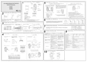
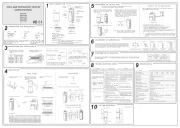
Bevægelsesdetektor
DS-PDD15AM-EG2

| Mærke: | Hikvision |
| Kategori: | Bevægelsesdetektor |
| Model: | DS-PDD15AM-EG2 |
| Bredde: | 65.7 mm |
| Dybde: | 103.8 mm |
| Højde: | 45.5 mm |
| Vægt: | 100 g |
| Antal pr. pakke: | 1 stk |
| Opbevaringstemperatur (T-T): | -20 - 60 °C |
| Relativ luftfugtighed ved drift (H-H): | 10 - 90 % |
| Relativ luftfugtighed ved opbevaring (H-H): | 10 - 90 % |
| Driftstemperatur (T-T): | -10 - 55 °C |
| Forbindelsesteknologi: | Ledningsført |
| Placering: | Indendørs |
| LED-indikatorer: | Ja |
| Strømkilde type: | DC |
| Monteringstype: | Væg |
| Indgangsspænding: | 12 V |
| Sensortype: | Passiv infrarød (PIR) sensor/mikrobølgesensor |
| Strømforbrug: | 25 mA |
| Driftsfrekvens: | 24000 MHz |
| Alarmfunktion: | Ja |
| Opdagelsesafstand: | 15 m |
| Lys sensitivitet: | 6500 Lux |
| Installationshøjde (min.): | 1.8 m |
| Installationshøjde (maks.): | 2.4 m |
| Registreringsvinkel: | 85.9 ° |
Har du brug for hjælp?
Hvis du har brug for hjælp til Hikvision DS-PDD15AM-EG2 stil et spørgsmål nedenfor, og andre brugere vil svare dig
Bevægelsesdetektor Hikvision Manualer

28 Juli 2025
8 December 2024

8 December 2024
8 December 2024

10 September 2024
27 August 2024

10 August 2024

6 August 2024

5 August 2024

1 August 2024
Bevægelsesdetektor Manualer
- Berker
- Maxsa
- Chamberlain
- Festo
- Gira
- Axis
- Gigaset
- XQ-lite
- EQ3
- Somfy
- Nexa
- Chuango
- Inovonics
- Blaupunkt
- Wentronic
Nyeste Bevægelsesdetektor Manualer

20 December 2025

18 December 2025

16 December 2025

11 December 2025

10 December 2025

10 December 2025

9 December 2025

9 December 2025

8 December 2025

7 December 2025