RTH110B 69-1799 2/6/05 1/3
The RTH110B non-programmable thermostat can be used to con-
trol:
• a gas, fuel oil or electric furnace - 2 or 3 wires
• a central air conditioner - 2 or 3 wires
• a hot water system with or without pump - 2 wires
• a millivolt system - 2 wires
• a central heating and cooling system - 4 or 5 wires
Note: This thermostat is not compatible with heat pumps or multi-
stage systems.
Features
• System operating mode selection: heat, cool or off
• Fan operating mode selection: automatic or on (continuous)
• Programmable heating and cooling cycle lengths: 10, 12, 15, 20
or 30 minutes
• Temperature display in °F or °C
• Battery replacement indicator
IN ORDER TO AVOID ANY RISK OF ELECTRIC SHOCK, CUT
POWER TO THE HEATING SYSTEM.
nRemove the old thermostat to access the wires.
Attention: If the old thermostat was mounted onto an electrical box,
it was probably powered by 120/240 volts. In this case, this thermo-
stat cannot be used.
oIdentify and label each wire (with the corresponding letter on
the wire terminal) and remove them from the terminals.
pIf necessary, strip the end of each wire (maximum of 1/4 inch).
qWrap the wires around a pencil to prevent
them from falling into the wall.
rIf the hole in the wall is too big, insulate it
using a non-flammable material in order
to avoid air draughts behind the thermo-
stat.
For a new installation, choose a location approximately 5 feet
(1.5 m) above the floor and on an inside wall. Avoid draughty
areas (top of staircase, air outlet, etc.), dead air spots (behind
doors), direct sunlight or areas near concealed pipes or chim-
neys.
nRemove the thermostat faceplate.
oLoosen the locking screw to separate the thermostat from its
baseplate (the screw cannot be completely removed).
pTilt the thermostat upwards.
qMark and bore the appropriate mounting holes (or use the
existing holes). Insert the plastic anchors.
rPass the wires through the opening of the baseplate and fix the
baseplate to the wall using the screws provided.
The connection of the new thermostat should be similar to that of
the old thermostat; however, it can vary depending on the installa-
tion.
Note: The red jumper wire between the Rc and Rh terminals must
be removed in 2- or 5-wire installations. The jumper must be used in
3- or 4-wire installations if you wish to use the mode selector switch
for the fan.
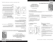
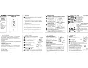
Display
Adjustment
buttons
System operating
mode selector Fan operating
mode selector
Rh Heating power supply
Rc Cooling power supply
W Heating signal
Y Cooling signal
G Fan