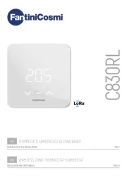
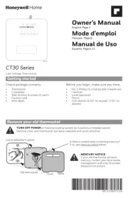
Honeywell RTH7600D1030/E Manual

Honeywell Termostat RTH7600D1030/E

Læs gratis den danske manual til Honeywell RTH7600D1030/E (60 sider) i kategorien Termostat. Denne vejledning er vurderet som hjælpsom af 16 personer og har en gennemsnitlig bedømmelse på 4.0 stjerner ud af 8.5 anmeldelser. Har du et spørgsmål om Honeywell RTH7600D1030/E, eller vil du spørge andre brugere om produktet?

Side 1/60
RTH7600 Series
Touchscreen Programmable Thermostat
69-2206ES-05
Installation Instructions
69-2206ES—05 ii
Installation is Easy
Label wires and remove your old thermostat
Install and wire your new thermostat
Set your new thermostat to match your heating/
cooling system
This thermostat works with virtually all System
Types
It is preset for the most common system
We are here to help.
Call 1-800-468-1502 for wiring
assistance before returning
the thermostat to the store.
1 69-2206ES—05
1Turn Off Power to Heating/
Cooling System
M28097
If you’ve already completed the Quick Start Guide, but
need to match your thermostat to your system type,
please turn to page 13.
69-2206ES 05 2
Remove old thermostat but leave wallplate with
wires attached.
2Remove Old Thermostat
M28099
Is there a sealed tube containing
mercury? If so, see back cover
for proper disposal instructions.
Leave wallplate
in place
Old thermostat
Cover
69-2206ES 05 4
Remove wallplate from the new thermostat and mount
onto wall.
M28073
4Separate Wallplate from
New Thermostat
Wallplate
69-2206ES 05 6
Simply match wire labels.
Remove metal jumper if you have both and wires.R Rc
M28070
W2
Y2
C
G
Y
W
RC
R
LABELED WIRES
SCREW
CONVENTIONAL
INSER WIRES T
THEN TIGHTEN SCREWS
WIRE HOLE
Y
G
R
W
CONVENTIONAL
6Connect Wires
Labels don’t match? See page 21.
Have a Heat Pump system? See pages 22–23.
We are here to help.
Call 1-800-468-1502 for wiring assistance.
69-2206ES 05 8
M27519
Install thermostat onto the wallplate on the wall.
8Install Thermostat onto Wallplate
9 69-2206ES—05
Turn the power back on to the heating/cooling system.
9Turn Power Back On
M28098
69-2206ES05 10
Go Back Next Done
6
15
2006
M27520
Done
M27521
10:10
Month Year Day
10 Set Time and Date
Press or to set month, then press NEXT.
Press or to set day, then press NEXT.
Press or to set year, then press DONE.
Press or to set time, then press DONE to save and
exit.
Advanced Installation
Thermostat setup .........................................................13–20
Entering setup options .................................................13–14
Set Date ..............................................................................15
Set System type ...........................................................16–18
Manual or Auto Changeover .............................................. 19
Temperature Format ...........................................................19
Daylight Saving Time .........................................................19
Filter Change Reminder .....................................................20
Smart Response Technology ............................................. 20
Clock Format ......................................................................20
Wiring 21–23 ............................................................................
Troubleshooting 24–25 ............................................................
Customer Assistance .........................................................26
RTH7600
13 69-2206ES—05
About your new thermostat
SETUP WIRING ASSISTANCE TROUBLESHOOTING
Step 1
Press and release the left button.
Step 2
Press and hold the center button until the screen
changes (approximately 5 seconds).
System setup
20
0120
System & Fan Schedule Clock & More
M27522
20
0120
System Fan Done
M27523
Advanced Installation Guide
69-2206ES05 14
About your new thermostat
SETUPWIRINGASSISTANCETROUBLESHOOTING
20
0120
Go Back Next Done
M27524
Function Setting
Press to change setting.
NOTE: Some functions in the following pages
may not appear due to previous selections
made.
Press NEXT to advance to
next function.
See pages 15–20 to change Function Settings.
Press DONE to save &
exit.
Changing settings
RTH7600
15 69-2206ES—05
About your new thermostat
SETUP WIRING ASSISTANCE TROUBLESHOOTING
NOTE: If you set the time and date as shown
on page 10, press to function 0170 and go NEXT
to page 16.
See page 14 to navigate between functions.
Function Settings & Options
0120 Year Setting
(first two
digits)
Press / to change the rst two
digits of the year:
20 = Year 20xx
21 = Year 21xx
0130 Year Setting
(second two
digits)
Press / to change the last two
digits of the year:
01 - 99 (i.e., 2001 - 2099)
0140 Month Setting Press / to change the current
month:
01 - 12 (i.e., January - December)
0150 Date Setting Press / to change the current
date:
01 - 31
System setup
Advanced Installation Guide
69-2206ES05 16
About your new thermostat
SETUPWIRINGASSISTANCETROUBLESHOOTING
See page 14 to navigate between functions.
Function Settings & Options
0170 Select System
Type
Press / to select your system
type:
1 Heat/cool: Gas, oil or electric
heating with - central air condi
tioning.
2 Heat pump: Heat pump with-
out backup or auxiliary heat.
3 Heat only: Gas, oil or electric
heat without - central air condi
tioning.
4 Heat only with fan: Gas, oil or
electric heat central air without
conditioning.
5 Hot water heat only (no fan):
Gas, oil or hot water heat with-
out central air conditioning.
6 Cool only: Central air condi-
tioning only.
7 Heat pump: Heat pump with
backup or auxiliary heating.
8 Heat/Cool Multiple stages:
2 heat stages (wires on and W
W2), 2 cooling stages (wires on
Y and Y2).
9 Heat/Cool Multiple stages:
2 heat stages (wires on and W
W2), 1 cooling stage (wire on
Y).
10 Heat/Cool Multiple stages: 1
heat stage (wire on ), 2 coolW-
ing stages (wires on and Y Y2).
System setup
RTH7600
17 69-2206ES—05
About your new thermostat
SETUP WIRING ASSISTANCE TROUBLESHOOTING
See page 14 to navigate between functions.
Function Settings & Options
0180 Heating Fan
Control
Press / to select your heating
system & fan control:
0 Gas or oil heat: Use this
setting if you have a gas or
oil heating system (system
controls fan operation).
1 Electric heat: Use this setting
if you have an electric heating
system (thermostat controls fan
operation).
0190 Heat Pump
Changeover
Valve (for heat
pumps only)
Press / to select whether your
changeover valve is used in heating
or cooling:
0 Cooling changeover valve:
Use this setting if you con-
nected a wire labeled “O” to
the O/B terminal (see page 22).
1 Heating changeover valve:
Use this setting if you con-
nected a wire labeled “B” to the
O/B terminal (see page 23).
System setup
Advanced Installation Guide
69-2206ES05 18
About your new thermostat
SETUPWIRINGASSISTANCETROUBLESHOOTING
See page 14 to navigate between functions.
Function Settings & Options
0240 Heating Cycle
Rate
Press / to select your heating
system:
5 Gas or oil furnace: Standard
gas/oil furnace (less than 90%
efficiency).
9 Electric furnace: Electric
heating systems.
3 Hot water or high-efficiency
furnace: Hot water system or
gas furnace (more than 90%
efficiency).
1 Gas/oil steam or gravity
system: Steam or gravity heat
systems.
0270 Emergency
Heat Cycle
Rate (heat
pumps only)
Press / to select your heating
system:
9 Electric furnace: Electric
heating systems.
5 Gas or oil furnace: Standard
gas/oil furnace (less than 90%
efficiency).
3 Hot water or high-efficiency
furnace: Hot water system or
gas furnace (more than 90%
efficiency).
1 Gas/oil steam or gravity
system: Steam or gravity heat
systems.
System setup
RTH7600
19 69-2206ES—05
About your new thermostat
SETUP WIRING ASSISTANCE TROUBLESHOOTING
See page 14 to navigate between functions.
Function Settings & Options
0300 Manual/Auto
Changeover
Press to select manual or /
automatic changeover:
0 Manual changeover (Heat/Cool/
Off).
1 Automatic changeover (Heat/
Cool/Auto/Off). Automatically
turns on Heat or Cool based
on room temperature. Note:
System maintains minimum 3°F
difference between heat and
cool settings.
0320 Temperature
Format (°F/°C)
Press / to set the temperature
display format:
0 Fahrenheit
1 Celsius
0330 Daylight Sav-
ing Time On/
Off
Press / to select an option:
0 Off: No adjustment for daylight
saving time.
1 On: Auto-change to daylight
saving time (for areas that do
not use the new 2007 DST
calendar).
2 On: Auto-change to daylight
saving time (2007 and beyond,
for areas that use the new 2007
DST calendar).
System setup
Advanced Installation Guide
69-2206ES—05 20
About your new thermostat
SETUPWIRINGASSISTANCETROUBLESHOOTING
See page 14 to navigate between functions.
Function Settings & Options
0500 Furnace Filter
Change
Reminder
Press / to set the desired
reminder interval:
0 Off (no reminder)
1 Reminder after 10-day run time
(about 1 month)
2 Reminder after 30-day run time
(about 3 months)
3 Reminder after 60-day run time
(about 6 months)
4 Reminder after 90-day run time
(about 9 months)
5 Reminder after 120-day run
time (about 1 year)
6 Reminder after 365-day run
time (about 3 years)
0530 Smart
Response®
Technology
Press / to turn this feature on or
off (see Operating Manual for more
information about this feature):
1 On
0 Off
0640 Clock Format Press / to set the clock display
format:
12 12-hour clock (i.e., 3:30 pm”)
24 24-hour clock (i.e., 15:30”)
Press DONE to save and exit setup.
System setup
RTH7600
21 69-2206ES—05
About your new thermostat
SETUP WIRING ASSISTANCE TROUBLESHOOTING
Alternate wiring (conventional systems)
If labels do not match terminals, connect wires as
shown here (see notes, below).
Remove metal jumper connecting and R Rc only
if you must connect and wires.both R Rc
If your old thermostat had both and R RH wires,
remove metal jumper. Connect the R wire to the
Rc terminal, and the RH wire to the terminal.R
If your old thermostat had only 1 or C C1
wire, connect it to the terminal. If your old C
thermostat had 2 or wires, wrap each C C1
separately with electrical tape and do not
connect them.
RC
R
W
Y
G
C
Y2
W2
Rc
R
W
Y
G
C
Y2
W2
M28076
2
3
2
Wiringconventional system
Advanced Installation Guide
69-2206ES05 22
About your new thermostat
SETUPWIRINGASSISTANCETROUBLESHOOTING
Connect wires: Heat Pump
1. Match each labeled wire with same letter on new
thermostat.
2. Use a screwdriver to loosen screws, insert wires into
hole, then tighten screws.
3. If E Aux and do not each have a wire connected,
use a small piece of wire to connect them to each
other.
4. Push any excess wire back into the wall opening.
Labels don’t match?
If labels do not match letters on thermostat, see page
23.
M28104
Aux
E
L
C
G
Y
O/B
RC
R
LABELED WIRES
SCREW
HEAT PUMP
INSER WIREST
THEN TIGHTEN SCREWS
WIRE HOLE
Y
G
R
Aux
O
HEAT PUMP
Wiring—heat pump
RTH7600
23 69-2206ES—05
SETUP WIRING ASSISTANCE TROUBLESHOOTING
Alternate wiring (for heat pumps only)
Leave metal jumper in place, connecting & R Rc
terminals.
If your old thermostat had both and V VR wires,
stop now and contact a qualified contractor for
help.
If your old thermostat had separate and O B
wires, attach the wire to the terminal. If B C
another wire is attached to the terminal, Cstop
now and contact a qualified contractor for help.
If your old thermostat had and wires, Y1, W1 W2
stop now and contact a qualified contractor for
help.
If mustL terminal is used, terminal wire C be
connected (contact a contractor if there is no C
wire).
If E and terminals do not each have a wire Aux
connected, use a small piece of wire to connect
them to each other.
2
3
3
4
5
5
6
6
M28077
5
6
Wiring—heat pump
Advanced Installation Guide
69-2206ES05 24
Troubleshooting
SETUPWIRINGASSISTANCETROUBLESHOOTING
If you have difficulty with your thermostat, please try
the following suggestions.
Most problems can be corrected quickly and easily.
Display is blank Make sure fresh AA alkaline batteries
are properly installed (see
page 7).
Cannot change
system setting
to Cool
Check Function 0170: System Type
to make sure it is set to match your
heating and cooling equipment (see
page 16).
Fan does not
turn on when
heat is required
Check Function 0180: Heating Fan
Control to make sure it is set to match
your heating equipment (see page 17).
Heating system
is running in
cool mode
Check Function 0170: System Type
to make sure it is set to match your
heating and cooling equipment (see
page 16).
Red light is on If thermostat is in Emergency Heat
mode the red light is normal. It shows
that the thermostat is in emergency
heat mode.
If thermostat is not in Emergency Heat
mode, contact a qualied service con-
tractor for repair.
RTH7600
25 69-2206ES—05
Troubleshooting
SETUP WIRING ASSISTANCE TROUBLESHOOTING
Heating or cool-
ing system does
not respond
Press to set system to Heat. SYSTEM
Make sure the temperature is set higher
than the Inside temperature.
Press to set system to Cool. SYSTEM
Make sure the temperature is set lower
than the Inside temperature.
Check circuit breaker and reset if
necessary.
Make sure power switch at heating &
cooling system is on.
Make sure furnace door is closed
securely.
Wait 5 minutes for the system to
respond.
“Wait” appears
on the screen
Compressor protection feature is
engaged. Wait 5 minutes for the system
to restart safely, without damage to the
compressor.
Heat pump is-
sues cool air in
heat mode, or
warm air in cool
mode
Check Function 0190: Heat Pump
Changeover Valve to make sure it is
properly congured for your system
(see page 17).
Advanced Installation Guide
69-2206ES 05 26
SETUPWIRINGASSISTANCETROUBLESHOOTING
For assistance with this product, please visit
http://yourhome.honeywell.com
or call Honeywell Customer Care toll-free at
1-800-468-1502.
Customer assistance
27 69-2206ES—05
Honeywell warrants this product, excluding battery, to be free
from defects in the workmanship or materials, under normal use
and service, for a period of one (1) year from the date of purchase
by the consumer. If at any time during the warranty period the
product is determined to be defective or malfunctions, Honeywell
shall repair or replace it (at Honeywell’s option).
If the product is defective,
(i) return it, with a bill of sale or other dated proof of purchase, to
the place from which you purchased it; or
(ii) call Honeywell Customer Care at 1-800-468-1502. Customer
Care will make the determination whether the product should be
returned to the following address: Honeywell Return Goods, Dock
4 MN10-3860, 1885 Douglas Dr. N., Golden Valley, MN 55422, or
whether a replacement product can be sent to you.
This warranty does not cover removal or reinstallation costs. This
warranty shall not apply if it is shown by Honeywell that the defect
or malfunction was caused by damage which occurred while the
product was in the possession of a consumer.
Honeywell’s sole responsibility shall be to repair or replace the
product within the terms stated above. HONEYWELL SHALL
NOT BE LIABLE FOR ANY LOSS OR DAMAGE OF ANY KIND,
INCLUDING ANY INCIDENTAL OR CONSEQUENTIAL DAMAGES
RESULTING, DIRECTLY OR INDIRECTLY, FROM ANY BREACH
OF ANY WARRANTY, EXPRESS OR IMPLIED, OR ANY OTHER
FAILURE OF THIS PRODUCT. Some states do not allow the exclu-
sion or limitation of incidental or consequential damages, so this
limitation may not apply to you.
THIS WARRANTY IS THE ONLY EXPRESS WARRANTY
HONEYWELL MAKES ON THIS PRODUCT. THE DURATION OF
ANY IMPLIED WARRANTIES, INCLUDING THE WARRANTIES
OF MERCHANTABILITY AND FITNESS FOR A PARTICULAR
PURPOSE, IS HEREBY LIMITED TO THE ONE-YEAR DURATION
OF THIS WARRANTY.
Some states do not allow limitations on how long an implied war-
ranty lasts, so the above limitation may not apply to you. This
warranty gives you specific legal rights, and you may have other
rights which vary from state to state.
If you have any questions concerning this warranty, please
write Honeywell Customer Relations, 1985 Douglas Dr, Golden
Valley, MN 55422 or call 1-800-468-1502. In Canada, write Retail
Products ON15-02H, Honeywell Limited/ Honeywell Limitée, 35
Dynamic Drive, Toronto, Ontario M1V4Z9.
1-year limited warranty
5 69-2206ES—05
Monte la nueva placa de montaje utilizando los tornillos y
anclajes que se suministran.
5Coloque la placa de montaje
M28094
Taladre agujeros de 3/16 in. (4,8 mm) en paneles de yeso
Taladre agujeros de 3/32 in. (2,4 mm) en yeso
69-2206ES 05 6
Simplemente haga corresponder las etiquetas de los
cables.
Retire el empalme metálico si tiene los cables “Ry “Rc”.
MS28070
W2
Y2
C
G
Y
W
RC
R
CABLES ETIQUETADOS
TORNILLO
CONVENCIONAL
INSERTE LOS CABLES Y
APRIETE LOS RNILLOSTO
ORIFICIO DE
CABLEADO
Y
G
R
W
CONVENCIONAL
6Conecte los cables
¿Los rótulos no coinciden? Vea la página 21.
¿Tiene un sistema de bomba de calor? Ver páginas
22-23.
Estamos aquí para ayudarle.
Llame al 1-800-468-1502 para asistencia con el
cableado.
7 69-2206ES—05
M27518
Instale dos baterías alcalinas AA en la parte de atrás del
termostato.
M28101
Parte de atrás del termostato
Retire la lengüeta.
7Instale las baterías
69-2206ES 05 8
M27519
Instale el termostato en la placa de montaje en la pared.
8Instale el termostato en la placa
de montaje
9 69-2206ES—05
Active nuevamente el suministro eléctrico del sistema de
calefacción/aire acondicionado.
9Active nuevamente el
suministro eléctrico
M28098
11 69-2206ES—05
Si su tipo de sistema es:
Calor y frío de una sola etapa
¡Felicitaciones, p43-ya está listo!
Si su tipo de sistema es:
Calor y frío de etapas múltiples
Bomba de calor* sin calor de respaldo
Bomba de calor* con calor de respaldo
Solo calor
Solo frío
Continúe con la instalación avanzada
en la próxima página para adaptar el termostato a su
tipo de sistema.
*Bomba de calor —un acondicionador de aire que
proporciona enfriamiento en el verano y también funciona
en reversa en el invierno, proporcionando calor.
Si no está seguro del tipo de sistema que tiene o si
tiene otras preguntas, llámenos gratis al
1-800-468-1502.
Este termostato funciona con sistemas de 24 voltios o
750 mV. NO funciona con sistemas de 120/240 voltios.
11 Si su tipo de sistema es...
Guía de instalación avanzada
Configuración del termostato ...................................... 13–20
Ingreso de las opciones de configuración..................13–14
Ajuste de fecha ................................................................... 15
Seleccione el tipo del sistema .....................................16–18
Cambio manual o auto ....................................................... 19
Format de la température ..................................................19
Ahorro diurno ...................................................................... 19
Recordatorio de cambio del filtro de la estufa .................20
Smart Response Technology (activo o apagado) ............. 20
Formato del reloj ................................................................20
Cableado 21–23 .......................................................................
En caso de dificultades ...............................................24–25
Asistencia al cliente ...........................................................26
13 69-2206ES—05
WIRING ASSISTANCE TROUBLESHOOTINGWIRING ASSISTANCE TROUBLESHOOTING
About your new thermostat
RTH7600
CONFIGURACIÓN
Paso 1
Presione y sostenga el botón izquierdo.
Paso 2
Presione y sostenga el botón central hasta que cambie
la pantalla (aproximadamente 5 segundos).
Cómo cambiar la configuración
20
0120
System & Fan Schedule Clock & More
M27522
20
0120
System Fan Done
M27523


Produkt Specifikationer

Mærke: Honeywell
Kategori: Termostat
Model: RTH7600D1030/E

Har du brug for hjælp?

Hvis du har brug for hjælp til Honeywell RTH7600D1030/E stil et spørgsmål nedenfor, og andre brugere vil svare dig