INST
INST
INST
INSTINSTALLA
ALLA
ALLA
ALLAALLATION INSTRUCTIONS
TION INSTRUCTIONS
TION INSTRUCTIONS
TION INSTRUCTIONSTION INSTRUCTIONS
TL8100
TL8100
TL8100
TL8100 TL8100
7 DAY PROGRAMMABLE HYDRONIC THERMOSTAT
GUIDELINES
GUIDELINES
GUIDELINES
GUIDELINESGUIDELINES
TURN OFF PO
TURN OFF PO
TURN OFF PO
TURN OFF POTURN OFF POWER TO THE HEA
WER TO THE HEA
WER TO THE HEA
WER TO THE HEAWER TO THE HEA
TING SYSTEM A
TING SYSTEM A
TING SYSTEM A
TING SYSTEM ATING SYSTEM AT
T
T
T T
THE MAIN POWER P
THE MAIN POWER P
THE MAIN POWER P
THE MAIN POWER PTHE MAIN POWER P
ANEL
ANEL
ANEL
ANEL ANEL T
T
T
TTO A
O A
O A
O AO AVOID ELECTRICAL
VOID ELECTRICAL
VOID ELECTRICAL
VOID ELECTRICAL VOID ELECTRICAL
SHOCK. INSTALLATION SHOULD BE CARR
SHOCK. INSTALLATION SHOULD BE CARR
SHOCK. INSTALLATION SHOULD BE CARR
SHOCK. INSTALLATION SHOULD BE CARRSHOCK. INSTALLATION SHOULD BE CARRIED OUT
IED OUT
IED OUT
IED OUT IED OUT
BY AN ELECTRICIAN.
BY AN ELECTRICIAN.
BY AN ELECTRICIAN.
BY AN ELECTRICIAN. BY AN ELECTRICIAN.
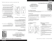
• For a new installation, choose a location about 5 ft.
(1.5 m) above the floor.
• The thermostat must be installed on an inside wall.
• Avoid locations where there are air drafts (top of
staircase, air outlet), dead air spots (behind a door),
direct sunlight, or concealed chimneys or stove pipes.
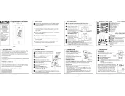
PROCEDURE
PROCEDURE
PROCEDURE
PROCEDUREPROCEDURE
1.
1.
1.
1.1. Loosen the captive screw securing the front mod-
ule to the rear module as shown in Fig. 1.
2.
2.
2.
2.2. Lift the lower part of the front module to remove it
from the rear module.
3.
3.
3.
3.3. Loosen the captive screw holding the terminal
cover and remove the cover.
4.
4.
4.
4.4. Pass the wires through the opening to the right of
the terminals. See Fig. 2. Secure the rear module
to an electrical box or to the wall using the supplied
wall anchors and screws.
5.
5.
5.
5.5. Connect the wires (see section “Thermostat Wir-
ing” on page 2). Use 12 AWG or smaller wire. 14
AWG is recommended for line voltage, 18 AWG is
recommended for 24 VAC.
6.
6.
6.
6.6. Install the terminal cover and tighten the screw.
7.
7.
7.
7.7. Configure the thermostat using the switches
located on the back of the front module (see sec-
tion “Thermostat Configuration” on page 3).
8.
8.
8.
8.8. Install the batteries (see section “Power-up” on
page 3).
9.
9.
9.
9.9. Mount the front module onto the rear module and
tighten the screw.
Fig. 1. I
Fig. 1. I
Fig. 1. I
Fig. 1. IFig. 1. Installation step
nstallation step
nstallation step
nstallation stepnstallation steps.
s.
s.
s.s.
Fig. 2. Routi
Fig. 2. Routi
Fig. 2. Routi
Fig. 2. RoutiFig. 2. Routing wires to thermostat.
ng wires to thermostat.
ng wires to thermostat.
ng wires to thermostat.ng wires to thermostat.