Honeywell TL8100A1008/U Manual
Læs gratis den danske manual til Honeywell TL8100A1008/U (12 sider) i kategorien Termostat. Denne vejledning er vurderet som hjælpsom af 9 personer og har en gennemsnitlig bedømmelse på 4.4 stjerner ud af 5 anmeldelser.
Har du et spørgsmål om Honeywell TL8100A1008/U, eller vil du spørge andre brugere om produktet?

Produkt Specifikationer
| Mærke: | Honeywell |
| Kategori: | Termostat |
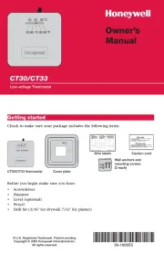
| Model: | TL8100A1008/U |
Har du brug for hjælp?
Hvis du har brug for hjælp til Honeywell TL8100A1008/U stil et spørgsmål nedenfor, og andre brugere vil svare dig
Termostat Honeywell Manualer

Termostat Manualer
- HomePilot
- Konyks
- OJ ELECTRONICS
- Robertshaw
- Fenix
- Drayton Erie
- EnerGenie
- Oregon Scientific
- Baxi
- SilverCrest
- AVM
- Homematic IP
- PECO
- Hager
- Devolo
Nyeste Termostat Manualer