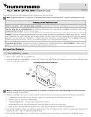
INSTALLATION OVERVIEW
Inside the boat there is often a channel or conduit used for other wiring, and this
can be used to route cables. Be sure to route the cable as far as practical from
the antenna cable of VHF radios or tachometer cables to reduce the possibility
of interference. The transducer cable should not be cut, and care should be used
not to damage the cable insulation.
Basic installation tasks that you must perform include the following:
•Install the control head (choose gimbal or in-dash mounting, where
in-dash mounting requires a separate purchase)
• (choose the installation method that matchesInstall the transducer
your transducer)
• See the guides includedInstall the optional-purchase accessories.
with each accessory.
•Test the complete installation
NOTE: To purchase accessories or any additional equipment for your control head
configuration, go to humminbird.com or contact Humminbird® Customer Service at
1-800-633-1468.
NOTE: The following accessories are not compatible with your unit: CannonLink™,
InterLink™, Remote Sonar Link™ (RSL), SmartCast®, WeatherSense®, and XM WX
Satellite Weather®. See our Web site at humminbird.com for the latest compatibility
information.
800 SERIES™ NOTE: If you are installing the Speed Sensor accessory (optional), you
will also need to purchase the Sonar/Speed Y-Cable. Contact Humminbird Customer
Service for details at 1-800-633-1468 humminbird.comor visit our Web site at .
SUPPLIES:
In addition to the hardware supplied with your transducer, you will need a
powered hand drill and various drill bits, various hand tools, including a ruler or
straightedge, a level, a 12" plumb line (weighted string or monofilament line), marker or
pencil, safety glasses and dust mask, and marine-grade silicone sealant.
NOTE:
When drilling holes in fiberglass hulls, it is best to start with a smaller bit and use
progressively larger drill bits to reduce the chance of chipping or flaking the outer coating.
CONTROL HEAD INSTALLATION
You have two choices for mounting your control head, , whereGimbal mounting
you use a surface on the boat, such as the dash, to mount the control head so
that it can be tilted up or down, or . In-dash mountingIn-dash mounting
requires a separate purchase. Contact Humminbird Customer Service for details.
Gimbal Mounting the Control Head
If you are gimbal mounting the control head, you can pre-assemble the unit in
order to plan the best mounting location.
Supplies: In addition to the hardware supplied with your control head, you will
need a powered hand drill and various drill bits, various hand tools, including a
Phillips head screwdriver, a socket wrench and a flat head screwdriver, a marker
or pencil, safety glasses and dust mask, and marine-grade silicone sealant.
1. Place the control head into the gimbal bracket. Make sure that the straight
side of the gimbal arm is against the back side of the control head.
2. Place a 1" (25 mm) diameter black washer on the gimbal knob and then
thread the knob and washer into the housing. Tighten the gimbal knob to
secure the control head to the mount. Repeat step 2 for the other side.
You can now place the control head in various locations to decide which is best
for mounting. Rotating the mounting bracket to the top of the control head will
allow for overhead mounting. The chosen mounting area should allow for
sufficient room so the control head can pivot through the full tilt range and allow
for easy removal and installation.
NOTE: You can drill the cable pass hole underneath the gimbal bracket, allowing you
to thread the cables through the knock-out holes in the mount; however, if you cannot
drill the hole directly under the mounting bracket, then you will need to drill the cable
pass hole behind the bracket and mount the hole cover there instead.
NOTE: When drilling holes in fiberglass hulls, it is best to start with a smaller bit and
use progressively larger drill bits to reduce the chance of chipping or flaking the outer
coating. Fill all holes with marine grade silicone sealant.
NOTE: You must have underside access to the mounting location to pass the cables
through to the surface. Also, make sure that the mounting surface is adequately
supported to protect the control head from excessive wave shock and vibration and
provide visibility while in operation.
3. Go to the installation instructions applicable to your transducer and
accessories. Make the required installations and then run the cables to your
control head mounting location. Do not cut any cabling (except the power
cable). If your cables are too short, extensions are available from your local
dealer or online from .humminbird.com
4. After the mounting location has been determined, loosen the gimbal knobs
and remove the control head from the gimbal bracket.
NOTE: Alternate hole patterns are available on the gimbal mounting bracket, and
may match existing holes on the boat. You may choose to use one of these alternate
hole patterns.
5. Place the gimbal bracket in the chosen position on the mounting surface and
mark the four mounting screw locations using a pencil or center punch.
Washer
1
Gimbal Knob
2
Gimbal Bracket
3
1
2
3
not available
1
not available
2
Power
3
32 4
Ethernet
COM (communications)
Transducer
4
5
6
1 5 6
NOTE:
Your transducer might not look exactly like the illustrations in this guide, but it
will mount in the same way. We encourage you to read this guide completely so that
you may understand the installation requirements.
NOTE:
Due to the wide variety of hulls, only general instructions are presented in this
installation guide. Each boat hull represents a unique set of requirements that should be
evaluated prior to installation. It is important to read the instructions completely and
understand the mounting guidelines before beginning installation.
6. Set the gimbal bracket aside and drill the four mounting screw holes using a
5/32" (4.0 mm) drill bit.
7a. If the cables must pass through a hole directly beneath the mounting
bracket, mark and drill an additional 1" (25 mm) hole centered between the
four mounting holes. Route the cables through the 1" hole. Place the hole
cover over the mounting surface hole, then use it to mark the position of the
two mounting screws. Remove the hole cover, drill the two mounting holes
using a 9/64" bit. Do not install the hole cover at this time.
or...
7b. If the cables cannot be routed directly beneath the mounting bracket,
mark and drill a 1" (25 mm) hole that will allow you to run the cables close to
the bracket. Pass the cables through the 1" (25 mm) hole, routing the cables
through the grommet and pressing the grommet into place. Place the hole
cover over the mounting surface hole, then use it to mark the position of the
two mounting screws. Remove the hole cover, drill the two mounting holes
using a 9/64" (3.5 mm) bit, fill them with marine-grade silicone, then replace
the hole cover and insert the #8 Phillips countersink wood screws.
Hand-tighten only.
8. Place the mounting bracket on the mounting surface aligned with the drilled
holes and fill the mounting holes with marine grade silicone sealant. Insert
the four #10 Slotted-Hex wood screws into the mounting holes.
Hand-tighten only.
9. If the cable pass through hole is beneath the mounting bracket, you will need
to install the hole cover after you have routed all cables. Place the hole cover
over the mounting bracket cable pass through hole and align with holes
drilled in step 7a. Insert the #8 Phillips countersink wood screws.
Hand-tighten only.
NOTE: Be sure that the cables pass through the slots on the hole cover and that there
is enough cable slack to allow for the control head to pivot through its full tilt range.
Extra cable slack will also help when connecting or disconnecting the cables.
10. Proceed to .Installing the Cable Connector Insert
Installing the Cable Connector Insert
1. Insert cable connectors into the proper recesses on the cable collector insert.
The cable connectors are keyed to prevent reverse installation, so be careful
not to force the connectors into the wrong slots. If you don’t have a cable for
every hole in the insert, install the blank plugs to protect the control head
from the weather.
800 SERIES NOTE: If you are installing the Speed Sensor accessory, insert the
Sonar/Speed Y-Cable connector into the Transducer slot on the cable connector
insert. Then, connect the transducer connector and speed sensor connector to the
corresponding connectors on the Y-Cable. The Y-Cable requires a separate purchase.
2. While holding cables in place in the
cable collector insert, thread the
cables through the slot in the
bottom of the cable collector cover.
Line up the cable collector insert
and cover, then slide the cover into
place on the insert.
NOTE: The tab on the Cable Collector
insert goes into the slot on the cover.
3. Attach the cable collector insert to
the cable collector cover using the 2
Phillips screws provided.
Plug Cable Connector Assembly
to Back of Control Head
Power
1
Ethernet
2
COM (communications)
3
Transducer
4
Cable Collector Insert
5
1 2 3 4
5
Cable Collector Insert
1
Screws
2
Cable Collector Cover
3
Tab on Insert
4
Slot on Cover
5
1
2
3
4
5
Inserting the Cables into the Cable Connector Insert
Assembling the Cable Collector
1
Cables Routed Directly Beneath Mounting Bracket
Gimbal Bracket
1
Hole Cover
2
2
1
Cables Routed Behind Mounting Bracket
3
Gimbal Bracket
1
Grommet
2
Hole Cover
3
2
1
3
2
Mounting Screws
1
Washer
2
Gimbal Mounting Bracket
3
4. Place the control head back onto the mounting bracket. Plug in the cable
collector assembly to the back of the control head. The cable connectors are
keyed to prevent reverse installation, so be careful not to force the connectors
into the wrong slots.
Once the cable collector and all cables are plugged into the back of the
control head, lock the assembly into place by threading the knurled screw
into the threaded insert on the back of the housing. Adjust the control head
to the desired viewing angle and secure by tightening the gimbal knobs.
NOTE: You may wish to dress the cabling with nylon wire ties in order to hold the
cables together and create a cleaner assembly.
Connecting the Control Head Power Cable to the Boat
A 6' (2 m) long power cable is included to supply power to the control head. You
may shorten or lengthen the cable using 18 gauge multi-stranded copper wire.
CAUTION! Some boats have 24 or 36 Volt electric systems, but the control head
MUST be connected to a 12 VDC power supply.
The control head power cable can be connected to the electrical system of the
boat at one of two places: a fuse panel usually located near the console, or
directly to the battery.
CAUTION! Make sure that the power cable is disconnected from the control head at
the beginning of this procedure.
NOTE: Humminbird is not responsible for over-voltage or over-current failures. The
control head must have adequate protection through the proper selection and
installation of a 3 Amp fuse.
NOTE: In order to minimize the potential for interference with other marine
electronics, a separate power source (such as a second battery) may be necessary.
TRANSOM TRANSDUCER
INSTALLATION
1.
Locating the Transducer Mounting Position
Turbulence: You must first determine the best
location on the transom to install the transducer. It is
very important to locate the transducer in an area
that is relatively free of turbulent water. Consider the
following to find the best location with the least
amount of turbulence:
• As the boat moves through the water,
turbulence is generated by the weight of the
boat and the thrust of the propeller(s) - either
clockwise or counter-clockwise. This turbulent
water is normally confined to areas immediately
aft of ribs, strakes or rows of rivets on the
bottom of the boat, and in the immediate area of
the propeller(s). Clockwise propellers create
more turbulence on the port side. On outboard
or inboard/outboard boats, it is best to locate
the transducer at least 15" to the side of the
propeller(s) (Figure 3).
• The best way to locate turbulence-free water is to view the transom
while the boat is moving. This method is recommended if maximum high-
speed operation (up to 65 mph) is a high priority. If this is not possible,
select a location on the transom where the hull forward of this location
is smooth, flat, and free of protrusions or ribs (Figure 1).
• On boats with stepped hulls, it may be possible to mount the transducer
on the step. Do not mount the transducer on the transom behind a step
to avoid popping the transducer out of the water at higher speeds. The
transducer must remain in the water for the control head to maintain the
sonar signal (Figure 2).
• If the transom is behind the propeller(s), it may be impossible to find an
area clear from turbulence, and a different mounting technique or
transducer type should be considered.
• If you plan to trailer your boat, do not mount the transducer too close to
trailer bunks or rollers to avoid moving or damaging the transducer
during loading and unloading of the boat.
NOTE: If you require a high-speed application (above 65 mph) and cannot find a
transom mount location that will work for your boat hull, a different mounting
technique or transducer type should be considered. See the FAQ (Frequently Asked
Questions) section of our Web site at humminbird.com or call Humminbird Customer
Service at 1-800-633-1468.
Side Imaging: The Side Imaging transducer has some special
requirements because of its side viewing capabilities:
• The Side Imaging transducer must NOT have anything
obstructing the ‘view’ of the side looking beams. Nothing can
be in the line of sight of these beams (not a hull, motor, or other
transducer, etc [Figure 4]).
NOTE: You may need to tilt the motor up and out of the way when using
the side looking beams.
• In order for the side beams to be displayed accurately, the
transducer must be mounted so that it is looking straight down
in the water when the boat is in the water.
Find a turbulence-free location at least 15" from the propeller(s) and
not in line with trailer bunks or rollers (Figure 3).
Level
NOTE: Traveling over 65 mph with the transducer in
the water is not recommended with the Side
Imaging® Transom Mount Transducer, as damage
might occur. If speed above 65 mph is critical,
contact Humminbird Customer Service for a different
mounting technique or transducer type at
1-800-633-1468 humminbird.comor .
Areas of Possible Turbulence
Rivets
Transom
Stepped Hull
Rib
Step
Figure 1
Figure 2
Strakes
Hull
1a. If a fuse terminal is available, use crimp-on type electrical connectors
(not included) that match the terminal on the fuse panel. Attach the
black wire to ground (-), and the red wire to positive (+) 12 VDC
power. Install a 3 Amp fuse (not included) for protection of the unit.
Humminbird is not responsible for over-voltage or over-current
failures.
or...
1b. If you need to wire the control head directly to a battery, obtain and
install an inline fuse holder and a 3 Amp fuse (not included) for the
protection of the unit. Humminbird is not responsible for over-voltage
or over-current failures.
GROUND
GROUND
GROUND
GROUND
GROUND
POSITIVE
POSITIVE
POSITIVE
POSITIVE
POSITIVE
NOTE: The hydrodynamic shape of your transducer allows
it to point straight down without deadrise adjustment
(Figure 5).
2.
Preparing the Mounting Location
In this procedure, you will determine the mounting
location and drill two mounting holes, using the
transducer mounting bracket as a guide.
1. Make sure that the boat is level on the trailer,
both from port to starboard and from bow to
stern, by placing your level on the deck of the
boat, first in one direction, then in the other.
2. Hold the mounting bracket against the transom
of the boat in the location you have selected
(Figure 6). Align the bracket horizontally, using
the level. Make sure that the lower corner of the
bracket does not protrude past the bottom of the
hull, and there is at least 1/4" clearance between
the bottom of the bracket and the bottom of the
transom for fiberglass boats, and 1/8" clearance
for aluminum boats (Figure 7).
NOTE: If you have a flat-bottomed aluminum boat, some
additional adjustment may be needed to accommodate
the rivets on the bottom of the boat (i.e. the gap may
need to be a little smaller than 1/8"). This will help you to
avoid excessive turbulence at high speeds.
NOTE: If your propeller moves clockwise (in forward, as
you're facing the stern of the boat from behind), mount
the transducer on the starboard side, and align the
bottom right corner of the mounting bracket with the
bottom of the boat. If your propeller moves counter-
clockwise (in forward, as you're facing the stern of the
boat from behind), mount the transducer on the port side,
and align the bottom left corner of the mounting bracket
with the bottom of the boat.
3. Continue to hold the bracket on the transom of
the boat, and use a pencil or marker to mark
where to drill the two mounting holes. Mark the
drill holes near the top of each slot, making sure
that your mark is centered in the slot (Figure 8).
4. Make sure that the drill bit is perpendicular to the
actual surface of the transom, NOT parallel to the
ground, before you drill. Using a 5/32" bit, drill the
two holes only to a depth of approximately 1".
NOTE: On fiberglass hulls, it is best to use progressively
larger drill bits to reduce the chance of chipping or flaking
the outer coating.
3.
Assembling the Transducer and Initial Mounting
In this procedure, you will assemble the transducer using the hardware
provided, then mount it and make adjustments to its position without locking it
in place.
NOTE: You will initially assemble the transducer and the pivot arm by matching the
two ratchets to a numbered position on the transducer knuckle. Further adjustments
may be necessary.
1a. refer to the chart below for theIf you already know your transom angle,
initial position to use to set the ratchets (Figure 9). If your transom is angled
at 14 degrees (a common transom angle for many boats) use position 1 for
the ratchets. In either case, go to step 2.
or...
1b. If you do not know your transom angle,
measure it using a plumb line (weighted nylon
string or monofilament line) exactly 12 inches
long. Hold the top of the plumb line against the
top of the transom with your finger, and wait
until the line hangs straight down (Figure 10).
Using a ruler, measure the distance from the
bottom of the plumb line to the back of the
transom, then use the chart (Figure 9).
NOTE: It is important to take your measurement in the
location shown in Figure 10, from exactly 12 inches down
from the top of the transom.
2. Place the two ratchets, one on either side of the
transducer knuckle, so that the beads on each
ratchet line up with the desired position number
on the knuckle (Figure 11a). If you are setting the
ratchets at position 1, the beads on each ratchet
will line up with the rib on the transducer knuckle
to form one continuous line on the assembly
(Figure 11b).
Transducer Knuckle Positions
Knuckle
Figure 11a
Figure 11d
Fitting the Pivot Arm Over the Ratchet
Beads
Ratchet
Rib at
position 1
Figure 11b
Ratchets Placed in Position 1
Rib
Ratchet
Bead
Figure 11c
Ratchets Placed in Position 2
Figure 4
Transducer Mount Position
Unobstructed View: The jack plate gives the transducer
safe distance from the motor and turbulence. The Side
Imaging has a clear view side-to-side.
Obstructed View: The transducer is too close to motor
turbulence, and the Side Imaging view is blocked by the
motor. The view cannot extend from side-to-side.
Figure 5
Deadrise Angle
Transom
Angle in
degrees
(°)
Measured
Distance (X)
Measuring the
Transom Angle
Plumb
line
Weight
Figure 10
Figure 9
-2 -1 0 1 2 3 4 5 6 7 8 9 10 11 12 13 14 15 16 17 18 19 20 21 22 23 24
Transom Angle (°)
Bead Alignment
Number 1 4 2 5 3 1 4 2 5
25 26 27
3
28 29 30
1
Measured Distance (x)
1.1cm
1/2“
0.0 cm
0“
2.5 cm
1“
4.3 cm
1 5/8“
5.9 cm
2 3/8“
7.6 cm
3“
9.3cm
3 5/8“
11.1cm
4 3/8“
12.9cm
5“
14.9cm
5 7/8“
16.9cm
6 5/8“
Using the Mounting Bracket to
Mark the Initial Drill Holes
Mark Initial
Drill Holes Figure 8
4th hole
3rd hole
Boat Hull Types Require
Different Mounting Positions
1/4" for fiberglass
1/8" for aluminum
Figure 7
Positioning the
Mounting Bracket
Level
Level
Figure 6
NOTE:
The third hole should not be drilled until the
angle and height of the transducer is finalized,
which you will not do until a later procedure.
NOTE: The ratchets are keyed. Make sure that the square teeth on each ratchet face
the square teeth on the transducer knuckle, and the triangular teeth face outward.
Hold the ratchets on the transducer knuckle with one hand and fit the pivot
arm over them until it snaps into place with the other hand. Refer to the
illustration (Figure 11d).
3. Put the pivot bolt through the assembly to hold it
in position and loosely install the nut, but do NOT
tighten the nut at this time (Figure 12).
CAUTION! Do not use a high speed driver on this
combination of fasteners. Hand tighten only.
4. Insert the pivot arm assembly into the mounting
bracket (Figure 13). Do NOT snap the assembly
closed, as you will need to access the mounting
bracket in the next step.
NOTE: If the pivot assembly is snapped closed over the
mounting bracket, use a flat head screwdriver or similar
tool to gently pry the assembly away from the mounting
bracket (Figure 14).
5. Align the mounting bracket transducer assembly
with the drilled holes in the transom. With a 5/16"
socket driver, mount the assembly to the transom
using the two #10 - 1" long screws provided
(Figure 15). Hand-tighten only!
NOTE: Make sure that the mounting screws are snug, but
do not fully tighten the mounting screws at this time to
allow the transducer assembly to slide for adjustment
purposes.
6. Snap the pivot arm down into place.
7. Adjust the initial angle of the transducer from back to front by rotating the
transducer until the side seam on the transducer is almost parallel with the
bottom of the boat, one click at a time in either direction (Figure 16).
8. Adjust the transducer assembly vertically, until
the seam on the leading edge of the transducer
(the edge closest to the transom of the boat) is
level and just slightly below the hull (Figure 17).
NOTE: The transducer has a natural downward slant of 4
to 5 degrees from leading edge (closest to the boat
transom) to trailing edge (farthest away from the boat).
Looking at the back of the transducer, the seam should be
slightly below the bottom of the hull.
9. Continue to adjust the transducer assembly until
the bracket is also level from port to starboard
(horizontally level as you look at the transducer
from behind the boat). (Figure 18)
10. Mark the correct position on the transom by
tracing the silhouette of the transducer mounting
bracket with a pencil or marker.
11. Tighten the pivot bolt, using the pivot screw and
nut to lock the assembly. Hand tighten only!
CAUTION! Do not use a high speed driver on this
combination of fasteners. Hand tighten only.
12. Snap open the assembly and hand-tighten the
two mounting screws, then snap the assembly
closed.
4.
Routing the Cable
The transducer cable has a low profile connector, which must be routed to the
point where the control head is mounted. There are several ways to route the
transducer cable to the area where the control head is installed. The most
common procedure routes the cable through the transom into the boat.
NOTE: Your boat may have a pre-existing wiring channel or conduit that you can use
for the transducer cable.
1. Unplug the other end of the transducer cable from the control head. Make
sure that the cable is long enough to accommodate the planned route by
running the cable over the transom.
CAUTION! Do not cut or shorten the transducer cable, and try not to damage the
cable insulation. Route the cable as far as possible from any VHF radio antenna
cables or tachometer cables to reduce the possibility of interference. If the cable is
too short, extension cables are available to extend the transducer cable up to a total
of 50'. For assistance, contact Humminbird Customer Service.
CAUTION! Do NOT mount the cables where the connectors could be submerged in
water or flooded. If cables are installed in a splash-prone area, it may be helpful to
apply dielectric grease to the inside of the connectors to prevent corrosion. Dielectric
grease can be purchased separately from a general hardware or automotive store.
NOTE: The transducer can pivot up to 90 degrees in the bracket. Allow enough slack
in the cable for this movement. It is best to route the cable to the side of the
transducer so the transducer will not damage the cable during movement.
2a. If you are routing the cable over the transom of the boat, secure the
cable by attaching the cable clamp to the transom, drilling 9/64" diameter
holes for #8 x 5/8" wood screws, then skip directly to procedure 5,
Connecting the Cable.Hand-tighten only!
or...
2b. If you will be routing the cable through a hole
in the transom, drill a 5/8" diameter hole above
the waterline. Route the cable through this hole,
then fill the hole with marine-grade silicone
sealant and proceed to the next step immediately
(Figure 19).
3. Place the escutcheon plate over the cable hole
and use it as a guide to mark the two escutcheon
plate mounting holes. Remove the plate, drill two
9/64" diameter x 5/8" deep holes, and then fill
both holes with marine-grade silicone sealant.
Place the escutcheon plate over the cable hole
and attach with two #8 x 5/8" wood screws.
Hand-tighten only!
4. Route and secure the cable by attaching the
cable clamp to the transom. Drill one 9/64"
diameter x 5/8" deep hole, then fill hole with
marine-grade silicone sealant, then attach the
cable clamp using a #8 x 5/8" screw.
Hand-tighten only!
Routing the Cable
Figure 19
Leveling the Mounting
Assembly Horizontally
Level
Level
Figure 18
Adjusting the Transducer
Mounting Position
Seam aligned
with boat hull Figure 17
Adjusting the Initial Transducer Angle
One click too low
Trailing edge
Correctly aligned
(transducer side seam
aligned with boat bottom)
One click too high
Figure 16
Leading edge
NOTE:
You will drill the third mounting hole and finalize the installation after
you route the cable and test and finish the installation in the following
procedures.
Mounting the Assembly to
the Transom
Figure 15
Inserting the Pivot Arm
Assembly Into the
Mounting Bracket
Figure 13
Figure 14
Inserting the Pivot Bolt
Figure 12
NOTE: If there is excess cable that needs to be gathered
at one location (as shown in the illustration), dress the
cable routed from both directions so that a single loop is
left extending from the storage location. Doubling the
cable up from this point, form the cable into a coil.
Storing excess cable using this method can reduce
electronic interference (Figure 20).
5.
Connecting the Cable
1. Insert the transducer cable into the appropriate slot on the cable connector
holder. See for details.Installing the Cable Connector Insert
NOTE: The cable connectors are labeled, and there are corresponding labels on the
connector holder on the rear of the control head. The slots are keyed to prevent
reversed installation, so be careful not to force the connector into the holder.
NOTE: If you are installing the Speed Sensor accessory (optional), you might also
need to purchase the Sonar/Speed Y-Cable. See Installing the Cable Connector
Insert for details.
6.
Test and Finish the Installation
Once you have installed both the control head and the transom transducer, and
have routed all the cables, you must perform a final test before locking the
transducer in place. Testing should be performed with the boat in the water.
1. Press POWER once to turn on the control head. If the unit does not power up,
make sure that the connector holder is fully seated in the receptacle and that
power is available.
2. If all connections are correct and power is available, the Humminbird control
head will enter Normal operation.
3. If the bottom is visible on-screen with a digital depth readout, the unit is
working properly. Make sure that the boat is in water greater than 2' but less
than the depth capability of the unit, and that the transducer is fully
submerged, since the sonar signal cannot pass through air.
NOTE: The transducer must be submerged in water for reliable transducer detection.
4. If the unit is working properly, gradually increase the boat speed to test high-
speed performance. If the unit functions well at low speeds, but begins to
skip or miss the bottom at higher speeds, the transducer requires adjustment.
5. If you have the correct angle set on the transducer, yet lose a bottom reading
at high speed, adjust the height and the running angle in small increments
to give you the ideal transducer position for your boat. First, adjust the height
in small increments (Figure 17).
NOTE: The deeper the transducer is in the water, the more likely that a rooster tail of
spray will be generated at high speeds, so make sure that the transducer is as high
as it can be and still be submerged in the water.
If you are still not getting good high speed readings, you may need to
disassemble the transducer mounting assembly and re-position the ratchets
(Figures 11a - 11d).
If you do change the transducer position, re-trace the position of the
mounting bracket before proceeding.
NOTE: It is often necessary to make several incremental transducer adjustments
before optimum high speed (up to 65 mph) performance is achieved. Due to the wide
variety of boat hulls, however, it is not always possible to obtain high speed depth
readings.
6. Once you have reached a consistently good sonar signal at the desired
speeds, you are ready to lock down the transducer settings. Force the pivot
to the Up position to gain access to the mounting screws, then re-align the
mounting bracket against the transom of the boat to match the traced
silhouette. Check the bracket position with the level again to make sure it is
still level, then mark the third mounting hole using a pencil or marker.
Unscrew and remove the mounting screws and the transducer assembly and
set aside.
7. Drill the third mounting hole, using a 5/32" drill bit. Use a marine-grade
silicone sealant to fill all three drilled mounting holes, especially if the holes
penetrated the transom wall.
NOTE: On fiberglass hulls, it is best to use progressively larger drill bits to reduce the
chance of chipping or flaking the outer coating.
8. Re-position the transducer assembly against the transom of the boat, then
hand-install all three screws. Make sure that the transducer location and the
pivot angle have not changed, then fully tighten all three mounting screws
(Figure 21). Snap the pivot back down. If you haveHand-tighten only!
performed the preceding procedures correctly, the transducer should be level
and at the right height for optimal operation.
7.
Locking Down the Transducer (Optional)
NOTE: You have the option to lock down the Two Piece Kick Up bracket if you do not
want the transducer to kick up. Please be aware, however, that the transducer can
be damaged if it is locked down and it strikes debris in the water.
1. To lock down the transducer, trace the position of
the mounting bracket. Force the pivot to the Up
position to gain access to the mounting screws,
then re-align the mounting bracket against the
transom of the boat to match the traced
silhouette. Check the bracket position with the
level again to make sure it is still level, then mark
the fourth mounting hole using a pencil or
marker (Figure 8). Unscrew and remove the
mounting screws and the transducer assembly
and set aside.
2. Drill the fourth mounting hole, using a 9/64" drill
bit. Use a marine-grade silicone sealant to fill all
four drilled mounting holes, especially if the
holes penetrate the transom wall.
3. Re-position the transducer assembly against the
transom of the boat, then hand install the first
three screws (two on the outside edges and one
in the 3rd mounting hole). Make sure that the
transducer location and the pivot angle have not
changed, then fully tighten all three mounting
screws (Figure 21). Hand-tighten only!
4. Snap the pivot back down. Install the #8 x 1"
wood screw into the 4th hole to lock down the
pivot arm (Figure 22). Hand-tighten only!
TROLLING MOTOR
TRANSDUCER INSTALLATION
Several styles of the transducer are compatible
with trolling motor mounting (Figure 23). If you
have a trolling motor bracket, refer to the
separate installation instructions that are
included with the bracket.
TROLLING MOTOR
TRANSDUCER OPTIONS
• You may purchase a Trolling Motor Adapter kit that will allow you to
mount the transducer on the trolling motor.
NOTE: 1-800-633-1468Call Humminbird Customer Service at for details and pricing,
or visit humminbird.com for more information.
Figure 23
Fully Tighten All Three
Mounting Screws
Figure 21
Figure 22
Storing Excess Cable
Figure 20
WARNING! Disassembly and repair of this electronic unit should only be performed
by authorized service personnel. Any modification of the serial number or attempt to
repair the original equipment or accessories by unauthorized individuals will void the
warranty.
WARNING! This product contains chemicals known to the State of California to
cause cancer and/or reproductive harm.
WARNING! This device should not be used as a navigational aid to prevent collision,
grounding, boat damage, or personal injury. When the boat is moving, water depth
may change too quickly to allow time for you to react. Always operate the boat at very
slow speeds if you suspect shallow water or submerged objects.
WARNING! Do not travel at high speeds with the unit cover installed. Remove the
unit cover before traveling at speeds above 20 mph.
ENVIRONMENTAL COMPLIANCE STATEMENT: It is the intention of Johnson
Outdoors Marine Electronics, Inc. to be a responsible corporate citizen, operating in
compliance with known and applicable environmental regulations, and a good
neighbor in the communities where we make or sell our products.
WEEE DIRECTIVE: EU Directive 2002/96/EC “Waste of Electrical and Electronic
Equipment Directive (WEEE)” impacts most distributors, sellers, and manufacturers of
consumer electronics in the European Union. The WEEE Directive requires the
producer of consumer electronics to take responsibility for the management of waste
from their products to achieve environmentally responsible disposal during the
product life cycle.
WEEE compliance may not be required in your location for electrical & electronic
equipment (EEE), nor may it be required for EEE designed and intended as fixed or
temporary installation in transportation vehicles such as automobiles, aircraft, and
boats. In some European Union member states, these vehicles are considered outside
of the scope of the Directive, and EEE for those applications can be considered
excluded from the WEEE Directive requirement.
This symbol (WEEE wheelie bin) on product indicates the product must not
be disposed of with other household refuse. It must be disposed of and
collected for recycling and recovery of waste EEE. Johnson Outdoors Marine
Electronics, Inc. will mark all EEE products in accordance with the WEEE
Directive. It is our goal to comply in the collection, treatment, recovery, and
environmentally sound disposal of those products; however, these requirements do
vary within European Union member states. For more information about where you
should dispose of your waste equipment for recycling and recovery and/or your
European Union member state requirements, please contact your dealer or distributor
from which your product was purchased.
© 2013 Johnson Outdoors Marine Electronics, Inc. All rights reserved.
CONTACT UMMINBIRDH
Contact Humminbird Customer Service in any of the following ways:
Web site:
humminbird.com
E-mail:
service@humminbird.com
Telephone:
1-800-633-1468
Direct Shipping:
Humminbird
Service Department
678 Humminbird Lane
Eufaula, AL 36027 USA
Hours of Operation:
Monday - Friday
8:00 a.m. to 4:30 p.m. (Central Standard Time)
HUMMINBIRD®
INSTALLATION GUIDE
532218-1_A