Other items that are needed (not included)
Prepare the required parts for each installation method before starting the installation. The following
are the requirements for the various installation methods.
Prepare the foundation of the installation site, installation support, and any other installation setting
with heavy salt damage resistance treatment.
AWhen hanging the camera from ceiling
Use the ceiling mount bracket (WV-Q121BS
BWhen installing the camera on a wall
Use the wall mount bracket (WV-Q122AS
Preparations before installation
Insert an SD memory card as occasion demands.
For the detailed procedures of inserting and removing an
SD memory card, refer to Important Information on the
① Loosen 2 SD slot cover fixing screws (M4) using a
Phillips screwdriver, and open the SD slot cover.
② Insert an SD memory card in the SD slot. Push in
straight until the end and confirm that a clicking sound
is heard. Take your ngers off the SD memory card
and check that its back end does not protrude over
③ Attach the SD slot cover again.
Recommended tightening torque of the SD slot cover
xing screws: 1.38 N·m {1.02 lbf·ft}
*1 For details on procedure for attaching mount bracket and
camera, read the operating instructions of each mount bracket.
The installation tasks are explained using 4 steps.
• Remove the camera using the reverse order of the installation procedures.
Cable cover 1 pc. ........................................................
Waterproof tape 1 pc. ..................................................
RJ45 waterproof connector cover 1 pc. ......................
RJ45 waterproof connector cap 1 pc. .........................
Rain wash coating label 1 pc. ......................................
8P alarm cable 1 pc. ...................................................
24 V AC power supply connector kit 1 set ....................
(Power supply connector housing: 1 pc., Contact: 3 pcs.)
.................................. 5 pcs.
Locking washers 5 pcs. ...............................................
Installation Guide (this document) 1 pc. .......................
IMPORTANT SAFETY INSTRUCTIONS 1 pc. ...............
.......................................................... 1 pc.
........................................................ 1 pc.
The CD-ROM contains the several kind of operating instructions and different kinds of tool software programs.
*2 This label may be required for network management. Use caution not to lose this label.
*3 The screws are necessary when installing the camera on a separately sold mount bracket.
The following parts are used during installation procedures.
Model No. WV-X6533LNS, WV-S6532LNS
• To prevent injury, this apparatus must be securely
attached to the wall/ceiling in accordance with the
installation instructions.
• All work related to the installation of this product
should be made by qualified service personnel or
• The installation shall be carried out in accordance
with all applicable installation rules.
• The connections should comply with local electri-
• Batteries (battery pack or batteries installed) shall
not be exposed to excessive heat such as sun-
• This equipment is compliant with Class A of
CISPR 32. In a residential environment this equip-
ment may cause radio interference.
• Operation of this equipment in a residential envi-
ronment could cause radio interference.
• The network camera is only intended for a con-
nection to an ethernet or PoE+ network without
routing to the outside plant.
• RISK GROUP 2 IR emitted from this product.
Avoid eye exposure. Use appropriate shielding or
Disposal of Old Equipment and Batteries
Only for European Union and countries with recycling systems
These symbols on the products, packaging, and/or accompanying documents mean that used
electrical and electronic products and batteries must not be mixed with general household
For proper treatment, recovery and recycling of old products and used batteries, please take
them to applicable collection points in accordance with your national legislation.
By disposing of them correctly, you will help to save valuable resources and prevent any
potential negative effects on human health and the environment.
For more information about collection and recycling, please contact your local authority.
Penalties may be applicable for incorrect disposal of this waste, in accordance with national
Note for the battery symbol (bottom symbol)
This symbol might be used in combination with a chemical symbol. In this case it complies with
the requirement set by the Directive for the chemical involved.
: Caution, infrared radiation
: Alternating current symbol
• Before attempting to connect or operate this product, please read these instructions carefully and
save this manual for future use.
• For information about the basic description of this product, refer to the Important Information on
the provided CD-ROM. For information about how to perform the settings and how to operate the
camera, refer to the Operating Instructions on the following our support website.
https://i-pro.com/global/en/surveillance/documentation_database
• Before reading this manual, be sure to read the Important Information.
The model number and serial number of this prod-
uct may be found on the surface of the unit.
You should note the model number and serial
number of this unit in the space provided and
retain this book as a permanent record of your
purchase to aid identification in the event of theft.
NOTE: This equipment has been tested and found
to comply with the limits for a Class A digital device,
pursuant to Part 15 of the FCC Rules. These limits
are designed to provide reasonable protection
against harmful interference when the equipment is
operated in a commercial environment. This equip-
ment generates, uses, and can radiate radio fre-
quency energy and, if not installed and used in
accordance with the instruction manual, may cause
harmful interference to radio communications.
Operation of this equipment in a residential area is
likely to cause harmful interference in which case
the user will be required to correct the interference
FCC CAUTION: Changes or modifications not
expressly approved by the party responsible for
compliance could void the user's authority to oper-
Supplier’s Declaration of conformity
Model No. : WV-X6533LNS, WV-S6532LNS
8550 Fallbrook Drive, Suite 200 Houston,
Support Contact : 1-800-513-5417
This device complies with part 15 of FCC Rules.
Operation is subject to the following two conditions :
(1)This device may not cause harmful interference,
and (2) this device must accept any interference
received, including interference that may cause
Important safety instructions
1) Read these instructions.
2) Keep these instructions.
4) Follow all instructions.
Do not install near any heat sources such as radiators, heat registers, stoves, or other apparatus (including
amplifiers) that produce heat.
6) Only use attachments/accessories specified by the manufacturer.
7) Use only with the cart, stand, tripod, bracket, or table specified by the manufacturer, or sold with the
apparatus. When a cart is used, use caution when moving the cart/apparatus combination to avoid injury
8) Unplug this apparatus during lightning storms or when unused for long periods of time.
9) Refer all servicing to qualified service personnel. Servicing is required when the apparatus has been dam-
aged in any way, such as power-supply cord or plug is damaged, liquid has been spilled or objects have
fallen into the apparatus, the apparatus has been exposed to rain or moisture, does not operate normally,
Before requesting service, refer to “Troubleshooting” of Important Information in the CD-ROM
and Operating Instructions on our support website. Then, confirm the trouble.
Included Installation Instructions
This product contains open source software licensed under GPL (GNU General Public License),
LGPL (GNU Lesser General Public License), etc.
Customers can duplicate, distribute and modify the source code of the software under license of
Refer to the “readme.txt” file on the provided CD-ROM for further information about open source
software licenses and the source code.
Please note that we shall not respond to any inquiries regarding the contents of the source code.
Product documentation is composed of the following documents.
Installation Guide (this document): Explains installation, mounting, cable connections, and
network connections. This manual uses the WV-X6533LNS as an example in the explanations.
Important Information (included in the CD-ROM):
Provides basic information about the prod-
uct such as Precautions for installation, Parts and functions, etc..
Operating Instructions (on our support website): Explains how to perform the settings and
how to operate this camera.
"<Control No.: C****>" used in this document should be used to search for information on our support website
(https://i-pro.com/global/en/surveillance/training_support/support/technical_information) and will guide you to
• The external appearance and other parts shown in this manual may differ from the actual
product within the scope that will not interfere with normal use due to improvement of the
• SDXC/SDHC/SD memory card is described as SD memory card.
• Refer to our support website
https://i-pro.com/global/en/surveillance/training_support/support/
technical_information <Control No.: C0120>
the minimum pull-out strength.
• Prepare four mounting screws (M10) to be mounted on ceiling or
• Select screws according to the material of the location that the
camera will be mounted to. In this case, wood screws and nails
• Please consider using anti-corrosive mounting screws or caulking.
• If the mounting location such as plaster board is too weak to
support the total weight, the area shall be sufficiently reinforced.
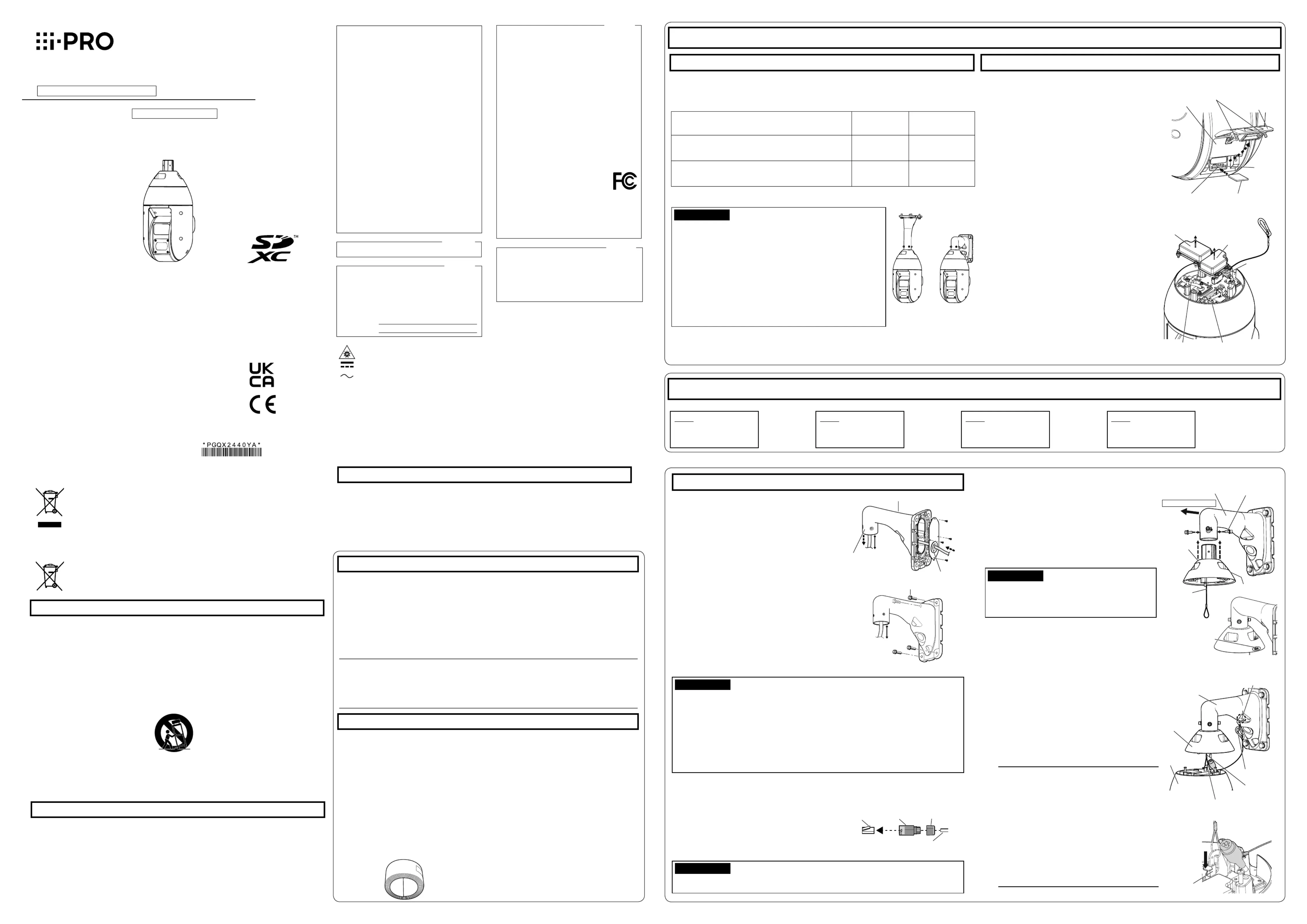
Prepare the cables from camera side.
When the only necessary connection to
camera is an Ethernet cable
Do not remove the cable case (2 positions),
When using 24 V AC, EXT I/O device, or
Using a Phillips screwdriver detach each cable
case fixed to the top of the camera by 4
screws (M4), and pull out the cable stored
inside. Discard the cable case.
SD slot cover fixing screws
(Heavy salt damage resistance)
For professional use only
Fixing screws (4 pcs.) (M10: locally procured)
Step1 Fix the mount bracket and hang the camera
Here explains an example of installation on a wall
using wall mount bracket (
installation information and procedure, refer to
operating instructions of each mount bracket.
Process the installation surface.
Decide the attachment position and bore holes for
screws or anchors on the wall and a hole for wiring
Pass a cable into mount bracket and fix it
on the installation surface.
Insert the cables coming from installation surface from rear
surface of mount bracket to internal and pull them out from
camera attachment port (cable cover attachment side).
When passing the cables into mount bracket, take
care not to apply unreasonable force to the cables.
Apply waterproof treatment to the drilled installation
surface and the cap of the mount bracket back-
③ Attach the mount bracket to wall surface using
fixing screws (4 pcs.) (M10: locally procured).
Attach the cable cover (accessory) to the
① Fix the cable cover to the mounting bracket using
special hexagonal screws and locking washers by
tightening the screws using a hexagonal wrench
for M5 screw (locally procured).
Adjust the direction of the cable cover so that the
“REAR” mark of the cable cover points towards
Recommended tightening torque:
• Camera mounting screw (hexagon screw (M6))
be used. Use the special hexagon screw that has
a large washer included with the camera.
② Remove the tape as the installed auxiliary wire is
temporarily fixed to the inside of the cable cover
• After waterproofing the hole for fixing mount bracket, the port for pulling out the cable on
installation surface, and the cap part on rear surface of mount bracket, fix the mount
bracket on the installation surface.
• Fixing screw: Minimum pull-out strength (per 1 pc.)
WV-Q121BS 1411 N {317 lbf}
WV-Q122AS 823 N {185 lbf}
• Adjust the length of cable from camera attachment port of mount bracket to cable end to
180~190 mm {7-3/32 inches~7-15/32 inches}. (If the cable that is pulled out is too long,
storage after wiring becomes difficult. On the contrary, if it is too short, the cable cannot
reach to the camera when installing the camera. Adjust the cable length carefully.)
• The maximum length of the Ethernet cable (locally procured) is 100 m {Approx. 328 ft}, and
the external dimensions of it are from ø5 mm {ø3/16 inches} to ø6.5 mm {ø1/4 inches}.
Process the Ethernet cable (locally procured) and attach
the waterproof connector cover and cap (accessory).
First pass the Ethernet cable through the RJ45
waterproof connector cap (accessory) and then
through the RJ45 waterproof connector cover
(accessory). Next, use a specialized tool (locally
procured) to crimp the RJ45 plug (locally procured) to
the end of the Ethernet cable.
Ethernet cable (locally procured)
• The horizontal and vertical rotating parts of the
camera are fixed by tape. Do not remove the
tape until fixing of the camera is completed.
• The camera is not fixed. Take care not to hit
the camera against periphery.
• Retain a work space of 800 mm
or more from the cable cover to the ground
surface when you hang the camera from it.
• The installed auxiliary wire and the safety wire
are designed assuming the only camera is
suspended. Do not hang any object other than
Wire hook on the upper part of camera
Hang the camera from the installed auxiliary
wire of the cable cover, and attach the safety
wire to the mounting bracket.
① Move the camera to the installation location and
hitch the installed auxiliary wire of the cable cover
to the wire hook on the upper part of camera.
Next, lower the wire stopper to prevent the
installed auxiliary wire from coming off.
② Attach the safety wire of the camera to the wire
hook section of mount bracket.
For the safety wire attachment position, refer to
operating instructions of each mount bracket.
• Take care not to remove the rubber parts from inside the RJ45 waterproof connector cover (accessory).
For Europe and other countries:
i-PRO Co., Ltd. Fukuoka, Japan
i-PRO EMEA B.V. UK Branch
1010 Cambourne Business Park,
Authorised Representative in EU:
Laarderhoogtweg 25, 1101 EB