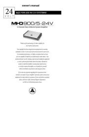
CONNECTION GUIDE
700W 5-Channel Class D System Amplier
with Integrated DSP
with
Thank you for purchasing a JL Audio amplifier for your sound system.
Your amplifier has been designed and manufactured to exacting
standards in order to ensure years of musical enjoyment. For maximum
performance, we highly recommend that you have your new amplifier
installed by an authorized JL Audio dealer. Your authorized dealer has
the training, expertise and installation equipment to ensure optimum
performance from this product. Should you decide to install the amplifier
yourself, please take the time to read this manual thoroughly to familiarize
yourself with its installation requirements and setup procedures.
If you have any questions regarding the instructions in this manual or any
aspect of your amplifier’s operation, please contact your authorized JL
Audio dealer for assistance. If you need further assistance, please contact
the JL Audio Technical Support Department at technical@jlaudio.com or
call (954) 443–1100 during business hours.
Installation Applications
This amplifier is designed for operation with 12 volt, negative-
ground electrical systems. Using this product in systems with positive
ground and/or voltages other than 12V may result in damage to the
product and will void the warranty. This product is not certified or
approved for use in aircraft.
Product Description
This is a five-channel, Class D system amplifier equipped with the second
generation of JL Audio’s NexD™ high-speed switching technology.
It is engineered to deliver reference-grade audio amplification with
outstanding efficiency and unprecedented, built-in processing power.
Instead of traditional analog processing controlled by knobs and switches,
VXi amplifiers feature an integrated DSP (Digital Signal Processor). The
amplifier and its integrated DSP are configured using an external device
(PC, Tablet or Phone), with the appropriate JL Audio TüN™ application
installed. (See section for more info.)What is TüN?
Planning Your Installation
It is important that you take the time to read this manual thoroughly
and that you plan your installation carefully. It is very easy to damage
expensive vehicle systems in modern automobiles. Never assume that you
have found appropriate wires without consulting a reliable wiring diagram
or without analyzing with proper test equipment. If you are uncomfortable
or unfamiliar with reading diagrams or testing methods, please enlist the
services of your authorized JL Audio dealer to perform the installation.
Your authorized dealer has the training, expertise and installation
equipment to ensure optimum performance from this product.
The
following are some considerations that you must take into account when
planning your installation.
Safety Considerations
• Install your amplifier in a dry, well-ventilated location that
does not interfere with your vehicle’s safety equipment
(air bags, seat belt systems, ABS brake systems, etc.).
• Do not mount the amplifier in the engine
compartment or in any areas of extreme heat.
• Securely mount the amplifier so that it does not come
loose in the event of a collision/sudden jolt or as a result
of repeated vibrations during normal operation.
• Check before drilling to make sure that you will not be drilling into
a fuel tank, gas/brake line, wiring harness, or other vital system.
• Do not run system wiring outside or underneath the
vehicle/vessel. This is an extremely dangerous practice,
which can result in severe damage/injury.
• Take the necessary precautions when making
connections to the vehicle’s battery.
• Protect all system wires from sharp edges by carefully routing them,
tying them down and using grommets and loom where appropriate.
• Secure all wiring as needed, using cable ties or wire clamps
to protect them from moving parts and sharp edges.
Cooling Efficiency Considerations
The outer shell of your JL Audio amplifier is designed to remove heat
from the amplifier circuitry. For optimum cooling performance, this outer
shell should be exposed to as large a volume of air as possible. Enclosing
the amplifier in a small, poorly ventilated chamber can lead to excessive
heat build-up and degraded performance. If an installation calls for an
enclosure around the amplifier, we recommend that this enclosure be
ventilated with the aid of a fan. In normal applications, fan-cooling is not
necessary. If mounting the amplifier under a seat, make sure there is at
least 1 inch (2.5 cm) of space above the amplifier’s outer shell to permit
proper cooling.
What is Included
(1) Amplifier (1) Power Connector
(1) Analog Input Harness (1) Speaker Output Harness
(1) JL Audio Badge (1) Subwoofer Output Harness
(1) USB A/B Cable (6 ft./1.8 m) (4) Corner Caps
(2) Black Hex Cap Machine Screws (1) Corner Cap Tool
(2) Silver Thumbscrews (1) 2.5 mm Hex Wrench
(1) Connection Guide (1) 3 mm Hex Wrench
JL Audio Badge
To complement the amplifier’s mounting orientation, the logo badge
includes a recessed key feature allowing it to be affixed at 90 degree
increments on the amplifier’s top. To install, remove the adhesive backing
and press the badge at the desired orientation.
Corner Cap Installation and Removal
The corner caps are designed to conceal the amplifier’s mounting holes
and hardware. To install, simply press a corner cap into each mounting
hole. To avoid scratching the amplifier’s chassis during removal, use the
included, plastic corner cap tool and lift below each cap.
Making Connections
VXi amplifiers utilize removable plugs and harnesses to make the
following connections:
• Power Connector
To connect the power, ground and remote turn-on wires to the amplifier,
back out the set screws on the connector using the supplied hex
wrenches. Strip back 3/8 inch (10 mm) of insulation from the end of each
wire and insert the bare wire into the receptacle on the power connector
plug, seating it firmly so that no bare wire is exposed. While holding each
wire in place, tighten each set screw firmly, taking care not to strip the
head of the screw. Install the power connector by plugging it into the
amplifier’s power connector receptacle, pushing firmly.
• Analog Input Harness
This harness includes connections for Signal Input (RCA plugs), Preamp
Outputs (RCA plugs), Remote Turn-On Output (wire lead) and Valet Input
(wire lead). Select either the included black hex cap machine screws or
the silver thumbscrews to secure the Analog Input Harness connector to
the amplifier.
• Speaker and Subwoofer Output Harnesses
These harnesses have output wire leads to connect with speaker cables.
Turn-On Mode
VXi amplifiers can be switched on and off using one of three methods,
configured by the “Turn On Mode” setting in the TüN™ Software Interface.
Refer to the table below for detailed info and decide which option is best
suited for your specific system.
Setting Mode Function Connection
Remote Conventional
(Preferred)
Turn-on/off controlled by your
source unit.
Connect your source unit +12V ’s
remote turn-on output to the
Power Connector’s Remote Turn-
On Input connection.
DC
Offset
DC Offset
Sensing
(Auto)
Automatically turns on/off by
detecting the presence of small
DC signal in OEM audio outputs.
This circuit senses the Analog
Input 1 only. Note: The sensitivity
of this circuit is designed for high-
level (speaker level) signals, not for
low-level (preamp level) signals.
Make sure the OEM audio outputs
contain midrange signals.
Signal
Signal
Sensing
(Auto)
Automatically turns on by
detecting full-range OEM audio
signals and turns off after
the signal is removed (varies,
depending on input signal levels).
3 Speaker Output Harness
Connect the speaker output leads to the corresponding speaker wires.
4 Subwoofer Output Harness
Connect the subwoofer output leads to the corresponding speaker wires.
Note: Two pairs of wire leads are included to facilitate multiple
subwoofer wiring. Both positive and both negative wire leads are
connected in parallel inside the harness.
5 JLid-COMM
Connect optional accessories (VXi-BTC, VXi-HUB, etc.) to this port.
6 JLid-CTRL
Connect optional DRC (Digital Remote Controller) wired controllers
to this port.
7 SD + Reset
Lift the dust cover to access the following utility functions:
Reset Buttons: Use a small pin to perform the following:
Reboot Amp - Press and release the right button.
Factory Reset (wipe memory, reboot amp) - Press and hold the left
button for 7 seconds.
DFU (Device Firmware Update) Mode: Press and release both
buttons simultaneously.
Micro SD Slot: For service/future expansion.
8 USB
This USB A/B port permits connection to a computer for configuration
and tuning, using the TüN™ Software.
9 DIGITAL-In
Toslink port accepts 2-channel digital audio signal from any optical
(S/PDIF) digital output, with a sample rate up to 192 kHz.
10 DIGITAL-Out
Provides a digital audio output (24 bit/96 kHz) that is not susceptible to
RF interference or noise-generating electrical conditions. By default, this
is a pass-through audio output, with no signal processing applied, and
intended for use with other equipment that have an optical (Toslink)
digital audio input (S/PDIF) port. Using the TüN™ Software Interface, you
may configure this output’s routing, equalization, output level and DRC
control functionality.
1 Power Connector
A. Run 4 AWG power wire from the positive (+12V) battery post to
the amplifier mounting location. If additional amplifiers are being
installed, run the appropriate gauge power wire for the combined,
maximum current draw, and install a fused distribution block near
the amplifiers.
B. An appropriate fuse (sold separately) at the main power wire(s) is
vital for vehicle safety. This fuse must be installed within 18 inches
(45 cm) of the battery post connection. If this is the only device con-
nected to this main wire, use a 60 A fuse. Do not install the fuse until
the power wire has been securely connected to the amplifier.
C. The ground connection should be made to a clean, solid metal
grounding point using 4 AWG wire, and kept as short as possible.
The metal surface of the grounding point should be sanded to create
a clean, metal-to-metal connection. For optimal grounding, we
recommend using a JL Audio ECS master ground lug (XB-MGLU). All
ground connections (source unit and amplifiers) should be made
at the same location.
D. The remote connection should be made to the source unit’s positive
(+12V) remote turn-on output. If your source unit does not have a
dedicated remote turn-on output, consider one of the alternative
turn-on options. (See Turn-On Mode section for more info.)
2 Analog Input Harness
The Analog Input Harness accepts the following connections:
Line-Level Analog Inputs: Six female RCA jacks feed a differential-
balanced input section, providing a high degree of input flexibility, and
retaining superior noise rejection. This type of input architecture also
allows the VX700/5i to cleanly accept any analog audio signals up to 16
VRMS, without using a line-output converter.
Preamp Outputs: Two female, RCA jacks deliver line-level, analog audio
outputs (Max 4 V RMS) that are compatible with most types of aftermarket
equipment. These are configured with the TüN ™ Software Interface.
Remote: This connection provides a positive (+12V) turn-on voltage
(475 mA limit) to activate other aftermarket equipment (similar to an
aftermarket head unit’s remote turn-on lead).
Valet: When connected to negative ground, this input activates the
Valet Mode Preset and will remain active until the ground connection is
removed. This preset is configured using the TüN ™ Software Interface and
will override any DRC controlled preset.
1 2 3
5 6 7 98 10
4