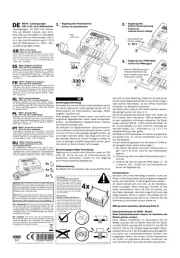
Kemo M240 Manual


Læs gratis den danske manual til Kemo M240 (4 sider) i kategorien Ikke kategoriseret. Denne vejledning er vurderet som hjælpsom af 10 personer og har en gennemsnitlig bedømmelse på 5.0 stjerner ud af 5.5 anmeldelser. Har du et spørgsmål om Kemo M240, eller vil du spørge andre brugere om produktet?

Side 1/4
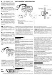
DE M240 | Leistungsregler
230 V/AC, 10 A, Multifunktion
Leistungsregler für 230 V/AC Verbrau-
cher wie Motoren, Lampen, viele dimm-
bare LEDs usw. Der Regler ist überlastfest
und kann über ein Potentiometer (100 K
lin.), über eine Steuerspannung (0 - 10 V)
oder mit PWM Signalen (0 - 100% , 100 -
10.000 Hz) geregelt werden.
GB M240 | Power Control
230 V/AC, 10 A, Multifunction
Power controller for 230 V/AC consumers such as motors,
lamps, many dimmable LEDs etc. The controller is over-
load-proof and can be controlled via a potentiometer (100
K lin.), a control voltage (0 - 10 V) or with PWM signals (0
- 100%, 100 - 10,000 Hz).
ES M240 | Regulador de potencia
230 V/AC, 10 A, multifunctión
Regulador de potencia para dispositivos consumidores
de 230 V/AC como motores, lámparas, etc. El regulador
es a prueba de sobrecargas y puede ser regulado a tra-
vés de un potenciómetro (100 K lin.), una tensión de
control (0 - 10 V) o con señales PWM (0 - 100%, 100
- 10.000 Hz).
FR M240 | Régulateur de puissance
230 V/AC, 10 A, multifonction
Régulateur de puissance pour consommateurs de 230
V/AC telles que moteurs, lampes, etc. Le régulateur est
protégé contre les surcharges et peut être commandé
par un potentiomètre (100 K lin.), une tension de com-
mande (0 - 10 V) ou avec des signaux PWM (0 - 100%,
100 - 10.000 Hz).
NL M240 | Vermogensregelaar
230 V/AC, 10 A, en is multi functioneel
Vermogens regelaar voor 230 V/AC motoren, lampen
etc. De regelaar is beveiligd tegen overbelasting en kann
via een potmeter (100 K lin.) of met een stuur spanning
(0 - 10V) of met PWM signaal (0 - 100%, 100 - 10.000
Hz) geregeld worden.
PL M240 | Regulator Mocy
230 V/AC, 10 A, wielofunkcyjny
Regulator mocy dla odbiorników 230 V/AC takich jak sil-
niki, lampy, itp. Regulator jest odporny na przeciążenie i
może być regulowany potencjometrem (100 k, liniowym),
napięciem stałym (0 10 V) DC lub sygnałem PWM (0 -
100%, 100 – 10.000 Hz).
PT M240 | Controlador de potência
230 V/AC, 10 A, multifunção
Controlador de potência para consumidor à 230 V/AC
como motores, mpadas etc. O regulador é à prova de
sobrecarga e pode ser controlado através de um poten-
ciômetro (100 K lin.), uma tensão de controle (0 - 10 V)
ou sinais PWM (0 - 100% , 100 - 10.000 Hz).
RU M240 | Регулятор мощности
230 В/переменный ток, 10 A,
многофункциональный
Для потребителей переменного тока 230 В таких,
как электромоторы, лампы и т.д. Регулятор устойчив
к перегрузкам и может управляться потенциометром
(100 кОм линейный), управляющим напряжением (0 -
10 В) или ШИМ-сигналами (0 - 100% , 100 - 10.000 Гц).
kann sich, je nach Belastung, erwärmen) und das es iso-
liert ist (keine Möglichkeit der Berührung mit den Fingern
oder anderen Körperteilen. Es sind offene Anschlüsse
vorhanden, die Netzspannung führen).
Das Modul sollte nahe an dem Gerät installiert werden,
das geregelt werden soll (max. 2 m).
Die Alu-Grundplatte des Moduls sollte nicht heißer als
60°C werden. Wenn das Modul < 800 W belastet wird,
ist kein zusätzlicher Kühlkörper erforderlich. Bei Belas-
tungen zwischen 800 W - 2.300 W sollte das Modul mit
der Alu-Grundplatte auf eine kühlende Unterlage ge-
schraubt werden. Z.B. : Kühlkörper ca. 12 x 9 x 2 cm
(Rippenkühlkörper) oder größer.
Das Modul hat 8 Flachstecker, mit denen es angeschlos-
sen werden kann 4 x 2,8 mm Flachstecker und 4 x 6,3
mm Flachstecker.
Je nach Anwendungszweck kann das Modul in 3 Metho-
den geregelt werden (siehe Zeichnungen):
1. Sie können das Modul mit einem Potentiometer re-
geln: 100 K lin (mind. 0,25 W). Das Potentiometer
liegt bei.
2. Ansteuerung über eine externe Steuerspannung. 0 -
10 V/DC
3. Ansteuerung über ein externes PWM Signal (3 - 24
V zwischen 100 - 10.000 Hz.) Die Impulsbreite be-
stimmt die Regelleistung.
Inbetriebnahme:
Nachdem alles vorschriftsmäßig verdrahtet wurde, das
Modul mit den Anschlüssen berührungssicher eingebaut
wurde, kann das Modul in Betrieb genommen werden.
Am Modul bendet sich eine LED, um den Betriebszu-
stand anzuzeigen. Wenn diese grün leuchtet, ist das
Modul betriebsbereit. Wenn die LED rot leuchtet, war
das Modul überlastet (das Modul regelt nicht mehr das
angeschlossene Gerät). In diesem Fall schalten Sie bit-
te die Betriebsspannung (230 V) ab. Entfernen Sie die
Überlastung und schalten danach wieder ein.
EMV-gerechter Anschluss (Zeichnung Seite 2)
Sicherheitshinweise für KEMO - Module
Diese Sicherheitshinweise müssen vor Anschluss des
Moduls gelesen werden!
Kemo Module entsprechen im Kaufzustand DIN EN
60065 und/oder DIN EN 60335 nebst DIN EN 55022
und DIN 55024 und/oder DIN EN 55014-1 und DIN EN
55014-2. Alle für die Fertigmontage benötigten Sicher-
heitselemente sind in der Montageanweisung aufgeführt
und dürfen aus sicherheitstechnischen Gründen nicht
ausgelassen werden. Den Einbau und die Inbetriebnah-
me dürfen nur autorisierte Personen vornehmen, die
auch die Haftung für eventuelle Schäden übernehmen.
P / Module / M240 / Beschreibung / 08036DI / Karton 1 / Einl. Ver. 001
www.kemo-electronic.de
1/4
DE | Entsorgung: Wenn das Gerät entsorgt werden soll,
darf es nicht in den Hausmüll geworfen werden. Es muss
an Sammelstellen für Fernsehgeräte, Computer usw.
entsorgt werden (bitte erkundigen Sie sich in Ihrem Ge-
meindebüro oder in der Stadtverwaltung nach Elektro-
nik-Müll-Sammelstellen).
GB | Disposal: This device may not be disposed with
the household waste. It has to be disposed at collecting
points for television sets, computers, etc. (please ask
your local authority or municipal authorities for these col-
lecting points for electronic waste).
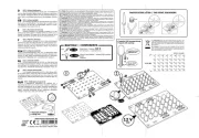
DE | Wichtig!
Modul zur Kühlung richtig montieren!
Die Alu-Grundplatte darf keinen mecha-
nischen Spannungen ausgesetzt werden
(keine Löcher bohren, nicht auf unebene
Kühläche schrauben usw.). Auf der Innen-
seite der Alu-Grundplatte sind direkt anlie-
gend empndliche elektronische Bauteile
montiert, die bei mechanischen Bewegun-
gen defekt werden und das Modul dann
nicht mehr arbeitet!
GB | Important!
Module for cooling mounted properly!
The aluminium base plate must not be ex-
posed to mechanical tension (do not drill
holes, do not screw on an uneven cooling
surface, etc.). Sensitive electronic compo-
nents are mounted directly adjacent on the
inside of the aluminium base plate, which
become defective in case of mechanical
movements and the module then won’t
work any longer!
*Schrauben nicht enthalten | screws not included
Hinweis: Bevor das Modul oder das Gerät in Betrieb
genommen oder zum ersten Mal installiert wird, muss
die ordnungsgemäße Funktion des Moduls oder des
Geräts von der Person überprüft werden, die das Teil
installiert oder in Betrieb nimmt.
Note: Before putting the module or device into opera-
tion, or installing it for the rst time, the proper functi-
on of the module or the device must be checked by a
person who installs the part or puts it into operation.
DE
Schaltungsbeschreibung:
Es handelt sich um eine Phasen-Anschnittsteuerung. Da-
mit können elektrische Lasten geregelt werden wie z.B.
Elektromotoren mit Kohle-Kollektor, Heizungen, Rüttel-
magnete, Lötkolben usw.
Nicht geregelt werden können Lasten, die bereits eine
eingebaute Regelelektronik haben sowie Energie-Spar-
lampen, Leuchtstofampen, Spaltpolmotoren, Motoren
mit Anlaufkondensator usw.
Die Drehzahl von Spaltpolmotoren (Synchronmotoren)
und von Motoren mit Anlaufkondensator können manch-
mal auch mit dem Leistungsregler geregelt werden, wie
uns Kunden berichtet haben. Das hängt vermutlich von
der jeweiligen Bauart ab. Unsere Aussage ist daher: es
muss im jeweiligen Einzelfall ausprobiert werden, gene-
rell können wir diese Funktion nicht zusagen.
Bestimmungsgemäßige Verwendung:
Regelung von ohmschen oder induktiven Lasten an 230
V/AC 50 - 60 Hz, bis max. 10 A Stromaufnahme. Die
elektrischen Verbraucher müssen für eine Regelung
durch Phasen-Anschnitt geeignet sein.
Aufbauanweisung:
Das Modul wird so eingebaut, das es gut belüftet ist (es
4x
4x
2x
2. Regelung über
Externe Steuerspannung
Control via
external control voltage
230 V
AC
1.Regelung über Potentiometer
Control via potentiometer
3. Regelung über PWM-Signal
Control via PWM signal
0 - 10 V
• Externes PWM Steuersignal
(Impulsbreitensteuerung)
• External PWM control signal
(Pulse-width control)
• Steuerspannung
• Control voltage
Poti
100 K lin.
• Sicherung
• Fuse
10A
Zu beachten sind die Montagehinweise, die der
Hersteller zum Komplettieren der Geräte mitlie-
fert. Alle Sicherheitseinrichtungen sind für den
dauerhaften Betrieb einzurichten und dürfen zur
eigenen Sicherheit nicht unbeachtet gelassen wer-
den, ebenso die Bedienungshinweise in der Bedie-
nungsanleitung.
Das Modul darf keinen zu hohen Temperaturen
(über 50ºC) und Feuchtigkeit ausgesetzt werden. In
gewerblichen Einrichtungen sind die Unfallverhü-
tungsvorschriften des Verbandes der gewerblichen
Berufsgenossenschaft für elektrische Anlagen und
Betriebsmittel zu beachten. Das Modul kann sich,
je nach Belastung, während des Betriebes erwär-
men. Es sollte daher so eingebaut werden, dass es
gut belüftet wird.
Kemo Baugruppen, die mit Spannungen 42 unter
V AC/DC arbeiten, dürfen von Kindern ab 8 Jah-
ren und von Personen mit eingeschränkten phy-
sischen, sensorischen oder geistigen Fähigkeiten,
unter Aufsicht betrieben werden.
Kemo Baugruppen, die mit Spannungen 42 über
V AC/DC arbeiten, dürfen von Jugendlichen ab 16
Jahren unter Aufsicht betrieben werden.
In Schulen, Ausbildungseinrichtungen, Hobby- und
Selbsthilfewerkstätten ist das Betreiben dieser Mo-
dule durch geschultes Personal verantwortlich zu
überwachen.
Leicht brennbare Flüssigkeiten und Teile (z.B. Vor-
hänge) dürfen nicht in der Nähe des Moduls und
der Anschlusskabel sein. Bei allen Bausätzen und
Modulen, die mit einer höheren Spannung als 25
V in Berührung kommen, müssen die VDE Sicher-
heitsbestimmungen beachtet werden! Der Einbau
bzw. die Inbetriebnahme darf nur durch eine fach-
kundige Person erfolgen! Zu den wichtigsten Sicher-
heitsbestimmungen gehören: Berührungsschutz
für alle metallischen Teile, die über 25 V Spannung
führen können. Zugentlastungen an allen Kabeln!
Im Falle eines Defekts können Bauteile oder das
Modul platzen! Das Modul bzw. die Platine muss so
eingebaut werden, dass in diesem Fall und auch im
Brandfall kein Schaden entstehen kann (Einbau in
geerdete Metallschränke oder geerdete Metallge-
häuse und Vorschalten von Sicherungen).
Technnische Daten:
Betriebsspannung: 220 - 230 V/AC 50 - 60 Hz |
Max. anschließbare Last: 10 Ampere (2.300 W)
| Regelungsart: | Einschaltung: Phasenanschnitt
Softstart | Betriebsanzeige, Anzeige Überlas-
tung: 2-Farbige LED | Regelungsmöglichkeiten:
mit Potentiometer 100 K lin oder Steuerspannung
0 - 10 V/DC oder PWM Signal 3 - 24 V 100 - 10.000
Hz | Der Steuersignaleingang ist komplett vom
Last-Regelkreis isoliert | Anschlüsse: Steckkon-
takte Flachstecker 6,3 mm und 2,8 mm | Maße:
ca. 87 x 60 x 33 mm
Typenschild M240 Leistungsregler
Kemo Electronic GmbH, Langen
Versorgungsspannung: 230 V ~, +/- 5%
Netzfrequenz : 50 / 60 Hz
Stromaufnahme : 0,005 A ~
Steuerlast max. : 2000 W
Einschaltdauer : 10A / 100 ED, S2
Schutzklasse II :
EG-Konformitätserklärung
Leistungsregler 230 V/AC, 10 A, Multifunktion M240
wird hiermit bestätigt, dass es den wesentlichen Schutzanforderun-
gen entspricht, die in den Richtlinien des Rates zur Angleichung der
Rechtsvorschriften der Mitgliedsstaaten über die elektromagneti-
sche Verträglichkeit (EMV-Richtlinie 2014/30/EU vom 19.09.2016)
und in der Niederspannungsrichtlinie 2014/35/EU festgelegt sind.
EN 55014-1 : 2012-05 Emission
EN 55014-2 : 2016-02 Störfestigkeit
EN 61000-3-2 : 2015-03 Netzoberschwingungen
EN 61000-3-3 : 2014-03 Netzschwankungen / Flicker
EN 60335-1 : 2012-10 Sicherheit elektrischer Geräte für
den Hausgebrauch und ähnliche
Zwecke
Das Produkt ist konform mit der RoHS-Richtlinie 2011/65/EU.
Diese Erklärung wird verantwortlich für den Hersteller / Importeur
Kemo Electronic GmbH
Leher Landstraße 20
D-27607 Geestland
Vukovic, Mato, Geschäftsführer
(Rechtsgültige Unterschrift)
GB
Circuit description:
It is a phase control circuit. Electrical loads, as e.g. electric motors
with carbon collector, heatings, jogging solenoids, soldering irons, etc.
can be controlled with it.
It is not possible to control loads with already built-in control
electronics, such as energy-saving lamps, uorescent lamps, shaded
pole motors, motors with starting capacitor, etc.
As customers reported to us, it is sometimes also possible to control
the rotational speed of shaded pole motors (synchronous motors)
and of motors with starting capacitor. This probably depends on the
respective style of construction. Therefore, our statement is: it has to
be tested in each individual case. We cannot promise this function in
general.
Intended use:
Control of ohmic or inductive loads at 230 V/AC 50 - 60 Hz, up to
max. 10 A current consumption. The electrical loads must be suitable
for phase angle control.
Assembly instructions:
Install the module in such a manner that it is well ventilated (it can
heat up depending on the load) and insulated (no possibility of contact
with ngers or other parts of the body). There are open connections
carrying supply voltage).
The module should be installed close to the device, which shall be
controlled (max. 2 m).
The aluminium base plate of the module should not heat to more
60°C. If the module is loaded with < 800 W, no additional heat sink
is required. For loads between 800 W - 2,300 W, the module with the
aluminium base plate should be screwed onto a cooling base. E.g.:
Built-in heat sink approx. 12 x 9 x 2 cm (ribbed heat sink) or larger.
The module has 8 at plugs by means of which it can be connected: 4
x 2.8 mm at plugs and 4 x 6.3 mm at plugs.
Depending on the application, the module can be controlled in 3
methods (see drawings):
1. You can control the module with a potentiometer: 100 K lin (min.
0.25 W). The potentiometer is included.
2. Control via an external control voltage. 0 - 10 V/DC
3. Control via an external PWM signal (3 - 24 V between 100 -
10,000 Hz.) The pulse width determines the controlling power
range.
Setting into operation:
After everything has been wired according to instructions and the
module with the connections has been installed so that it cannot be
touched, the module can be put into operation.
There is an LED on the module to indicate the operating status. If this
LED is green, the module is ready for operation. If the LED is red, the
module was overloaded (the module no longer controls the connected
device). In this case please switch off the operating voltage (230 V).
Remove the overload and switch on again afterwards.
Connection according to EMC (drawing page 2):
All components must be approved for an operating voltage of 240 V/
AC. The choke must be approved for the strength of current which the
module absorbs.
The above components are not attached to the module. With this
extreme mode of connection the module corresponds to the EMV-
guideline 2014/30/EU (Law of electromagnetic compatibility (EMV)).
Safety instructions for KEMO Modules
These safety instructions have to be read before connecting the
module!
In the condition of purchase the Kemo modules correspond to DIN
EN 60065 and/or DIN EN 60335 in addition to DIN EN 55022 and
DIN 55024 and/or DIN EN 55014-1 and DIN EN 55014-2. All safety
elements required for the nal assembly are listed in the mounting
instructions and must not be omitted for safety regulations. The
assembly and starting may only be carried out by authorized persons
who can also be held responsible for possible damage.
The mounting instructions supplied by the manufacturer for
completion of the appliances are to be observed. All safety facilities
are to be installed for permanent operation and must not be ignored
for personal safety. The same applies to the operating instructions
mentioned in the manufacturer‘s instructions.
The module must not be exposed to extreme temperatures (more
than 50°C) and humidity. The regulations for prevention of accidents
for electrical installations and operating material of the industrial
employer‘s liability insurance association are to be observed in
industrial facilities. The module may become warm during operation
depending on the load. Therefore, it is advisable to t it into a well
ventilated spot.
Kemo componentries functioning with voltages 42 V AC/DC below
may be operated by children from 8 years of age and by persons with
restricted physical, sensory or mental abilities under survey.
Kemo componentries functioning with voltages 42 V AC/DC may over
be operated by adolescents from 16 years of age under survey.
In schools, training centers and do-it-yourself workshops, the operation
of these modules is to be supervised reliably by trained personnel.
Never place this module and the supply lines close to combustible or
inammable materials (e.g. curtains). For all kits and modules which
come into contact with a voltage higher than 25 V, the VDE - safety
instructions must be observed! The installation resp. initial operation
may only be done by an expert! The most important safety instructions
are: Protection against accidental contact for all metallic parts which
can carry more than 25 V current. Strain reliefs at all cables! In case
of defect, components or the module can burst! Therefore the module
resp. the printed circuit board have to be installed in such a way that
in this case as well as in case of re no damage occurs (installation
into earthed metallic cupboards or earthed metallic casings and
superposing of safety fuses).
Technical data:
Operating voltage: 220 - 230 V/AC 50 - 60 Hz | Max. connectable
load: 10 Ampere (2,300 W) phase angle control | Control mode:
| Switching-on: | Operating display, overload display: soft start
2-coloured LED with potentiometer 100 K lin or | Control options:
control voltage 0 - 10 V/DC or PWM signal 3 - 24 V 100 - 10,000
Hz | The control signal input is completely isolated from the load
control circuit. | Connections: Plug contacts at plugs 6.3 mm and
2.8 mm approx. 87 x 60 x 33 mm| Dimensions:
ES
Descripción de la conmutación:
Se trata de un control por corte de onda. Con eso se pueden regular
cargas eléctricas como p.ej. motores eléctricos con colector de
carbón, calefacciones, solenoides de sacudida, soldadores, etc.
No se pueden regular cargas que p2-ya tienen una electrónica de
regulación instalada así como lámparas economizadoras de energía,
lámparas uorescentes, motores de fase dividida, motores con
capacitor de arranque, etc.
Como nuestros clientes han reportado, el número de revoluciones
de motores de fase dividida (motores sincrónicos) y de motores con
capacitor de arranque se pueden regular a veces con el regulador de
potencia. Eso depende probablemente de la forma de construcción
respectiva. Por consiguiente, nuestra declaración es: se debe probar
en el caso aislado. No podemos prometer esta función generalmente.
P / Module / M240 / Beschreibung / 08036DI / Karton 1 / Einl. Ver. 001 2/4
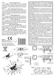
EMV-gerechter Anschluss:
Alle Bauteile müssen für eine Betriebsspannung von 240 V/AC zugelassen sein. Die Drossel muss für die Stromstärke, das Modul aufnimmt, zulässig sein. Die obigen Bauteile gehören nicht zum Lieferumfang des Moduls. Mit
dieser externen Beschaltung entspricht das Modul der EMV-Richtlinie 2014/30/EU vom 19.09.2016 (EMV, elektromagnetische Verträglichkeit).
DE | Eingang 240 V/AC, eine Sicherung vorschalten
GB | Input 240 V/AC, please superpose a safety fuse
ES | Entrada 240 V/AC, por favor, preconectar un fusible
FR | Entrée 240 V/AC veuillez intercaler un fusible de sécurité
NL | Ingang 240 V/AC, zekering voorschakelen
PL | Wejście 240 V/AC, podłączyć bezpiecznik
PT | Entrada 240 V / AC, conecte um fusível
RU | Вход 240 В~, подключите предохранитель
DE | Zum 240 V/AC-Eingang des Moduls
GB | Towards the 240 V/AC input of the module
ES | Hacia la entrada 240 V/AC del módulo
FR | Vers l‘entrée 240 V/AC du module
NL | Naar de 240 V/AC ingang van module
PL | Do wejścia modułu 240 V/AC
PT | Para a entrada de 240 V / AC do modulo
RU | К 240 В~ -входу модуля
DE | Stromkompensierte Drossel L1 = 2 x 6,8 mH
GB | Current-compensated choke L1 = 2 x 6,8 mH
ES | Choque de corriente compensado L1 = 2 x 6,8 mH
FR | Bobine de choc de courant compensé L1 = 2 x 6,8 mH
NL | Stroom begrensende spoel L1 = 2 x 6,8 mH
PL | Skompensowany dławik L1 = 2 x 6,8 mH
PT | Atolamento com compensação de corrente L1 = 2 x 6,8 mH
RU | Дроссель для компенсации тока L1 = 2x 6,8 мH
C1 10 nF Y2
C2 47 nF X2
C3 470 nF X2


Produkt Specifikationer

Mærke: Kemo
Kategori: Ikke kategoriseret
Model: M240

Har du brug for hjælp?

Hvis du har brug for hjælp til Kemo M240 stil et spørgsmål nedenfor, og andre brugere vil svare dig


Ikke kategoriseret Kemo Manualer

Kemo

Kemo B223 Manual

3 September 2024
Kemo

Kemo M135 Manual

3 September 2024
Kemo

Kemo M158 Manual

28 August 2024
Kemo

Kemo S093 Manual

28 August 2024
Kemo

Kemo B062 Manual

28 August 2024
Kemo

Kemo M079N Manual

22 August 2024
Kemo

Kemo M240 Manual

22 August 2024
Kemo

Kemo B185 Manual

16 August 2024
Kemo

Kemo M120 Manual

15 August 2024
Kemo

Kemo B042 Manual

15 August 2024

Ikke kategoriseret Manualer

Nyeste Ikke kategoriseret Manualer