Kimo ATE 310 Manual


Læs gratis den danske manual til Kimo ATE 310 (7 sider) i kategorien Ikke kategoriseret. Denne vejledning er vurderet som hjælpsom af 3 personer og har en gennemsnitlig bedømmelse på 4.5 stjerner ud af 2 anmeldelser. Har du et spørgsmål om Kimo ATE 310, eller vil du spørge andre brugere om produktet?

Side 1/7
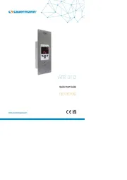
ATE 310
Quick Start Guide
www.sauermanngroup.com
ESEN FR
English
Quick Start Guide
Flush-mount multiparameter display
General features
Features of the housing
Used symbols
For your safety and in order to avoid any damage of the device, please follow the procedure described in
this document and read carefully the notes preceded by the following symbol:
The following symbol will also be used in this document, please read carefully the information notes
indicated after this symbol:
ATE 310
Connections
Electrical connections as per NFC15-100 standard
3 analogue inputs 0-5/10 V or
0/4-20 mA
Alternating display of 1 to 3
parameters
Digital RS485 ModBus RTU
input
3 audible and visual alarms
0-5 / 10 V
4-20 mA
Power supply
24 Vac/Vdc ±10%
Warning: risk of electric shock
Inputs 3 x 0/4-20 mA or 3 x 0-5/10 V; Common mode voltage < 30 Vac; Input impedance: 100 Ω
Galvanic isolation Between input and power supply
Consumption 4.32 VA
European directives 2014/30/UE EMC; 2014/35/UE Low voltage; 2011/65/EU RoHS II; 2012/19/UE WEEE
Electrical connection
Screw terminal block for cables from 0.05 to 1.5 mm
2
or from 30 to 16 AWG.
Carried out according to the code of good practice.
RS485
communication
Digital: ModBus RTU protocol, congurable communication speed from 2400 to 115,200 Bauds
Ethernet
communication
(optional)
Ethernet communication module enables transmission,
management and maintenance of the sensors through an
Ethernet network in 10 BASE-T and 100 BASE-TX LAN/WAN carrying the TCP/IP protocole. Additional consumption: 0.68 VA
Visual alarm Blinking of the value
Audible alarm Buzzer (70 dB at 10 cm)
Environment and type of
uid
Air and neutral gases
Conditions of use
(°C/%RH/m)
From -10 to +50 °C. In non-condensing condition.
From 0 to 2000 m.
Dimensions
Front face Brushed stainless steel 316 L
Back housing Flush-mount in stainless steel 304 L
Protection IP65 in front face
Weight 585 g
234 mm
92 mm
44 mm
42.5 mm
70 mm
196 mm
3.2 mm
218 mm
76 mm
69 mm
147.3 mm
Innovations
Connection to a computer in front face
Mini-DIN connection USB connection
Rear view
Ethernet connection
(option)
+-
+-
Power supply terminal block
ModBus
IN1
13 14 15
GND
or
or
For 24 Vdc power
supply models:
Power supply terminal block
+-
+-
B A
1 2 3
13 14 15
1 2 3 4 5 6 7 8 9 10 11 12
0/4-20 mA Current
GND – Ground
0-5/10 V Voltage
IN2
4 5 6
IN3
7 8 9
Neutral (N)~
Phase (L)~
10 11 12 10 11 12
10 11 12
24 Vdc
Power supply
+ -
+ -
+ -
+ -
+ -
+ -
1 2 3
Active type
sensor
24 Vac Power supply
class II
24 Vac230 Vac
Power supply
terminal block
10 11 12
N N
N
mA GND
IN1
V
L
L
L
Pe
~
~
24 Vac Power supply
24 Vac
230 Vac
10 11 12
N N
N L
L L
Pe
~
~
4 5 6 7 8 9 1 2 3 4 5 6 7 8 9
mA GND
IN2
V mA GND
IN3
V
+-
+-
+-
+-
+-
+-
mA GND
IN1
V mA GND
IN2
V mA GND
IN3
V
0/4-20 mA Current
GND – Ground
0-5/10 V Voltage
0/4-20 mA Current
GND – Ground
0-5/10 V Voltage
For 24 Vac power
supply models:
Active type
sensor
Active type
sensor
Active type
sensor
Active type
sensor
Active type
sensor
Only a trained and qualied technician can realise this operation.
To realise this connection, the device must NOT BE SUPPLIED.
For 24 Vdc power supply models: For 24 Vac power supply models:
0/4-20 mA current output connection: 0-5/10 V voltage output connection:
+-
+-
Power supply terminal block
ModBus
IN1
13 14 15
GND
or
or
For 24 Vdc power
supply models:
Power supply terminal block
+-
+-
B A
1 2 3
13 14 15
1 2 3 4 5 6 7 8 9 10 11 12
0/4-20 mA Current
GND – Ground
0-5/10 V Voltage
IN2
4 5 6
IN3
7 8 9
Neutral (N)~
Phase (L)~
10 11 12 10 11 12
10 11 12
24 Vdc
Power supply
+ -
+ -
+ -
+ -
+ -
+ -
1 2 3
Active type
sensor
24 Vac Power supply
class II
24 Vac230 Vac
Power supply
terminal block
10 11 12
N N
N
mA GND
IN1
V
L
L
L
Pe
~
~
24 Vac Power supply
24 Vac
230 Vac
10 11 12
N N
N L
L L
Pe
~
~
4 5 6 7 8 9 1 2 3 4 5 6 7 8 9
mA GND
IN2
V mA GND
IN3
V
+-
+-
+-
+-
+-
+-
mA GND
IN1
V mA GND
IN2
V mA GND
IN3
V
0/4-20 mA Current
GND – Ground
0-5/10 V Voltage
0/4-20 mA Current
GND – Ground
0-5/10 V Voltage
For 24 Vac power
supply models:
Active type
sensor
Active type
sensor
Active type
sensor
Active type
sensor
Active type
sensor


Produkt Specifikationer

Mærke: Kimo
Kategori: Ikke kategoriseret
Model: ATE 310

Har du brug for hjælp?

Hvis du har brug for hjælp til Kimo ATE 310 stil et spørgsmål nedenfor, og andre brugere vil svare dig


Ikke kategoriseret Kimo Manualer
Kimo

Kimo KNT 320 Manual

17 September 2025
Kimo

Kimo PST Manual

16 September 2025
Kimo

Kimo ATE 310 Manual

16 September 2025
Kimo

Kimo TM 210-R Manual

16 September 2025
Kimo

Kimo CP 210-R Manual

16 September 2025
Kimo

Kimo COT 212-R Manual

16 September 2025
Kimo

Kimo CA 310 Manual

2 September 2025
Kimo

Kimo LR 110 Manual

2 September 2025
Kimo

Kimo CO2ST-S Manual

2 September 2025
Kimo

Kimo TST Manual

2 September 2025

Ikke kategoriseret Manualer

Nyeste Ikke kategoriseret Manualer

Vulcan

Vulcan VBP15SL Manual

17 September 2025
Rocktrail

Rocktrail IAN 463536 Manual

17 September 2025
Vestil

Vestil LPRO-36-16-4 Manual

17 September 2025
Vestil

Vestil CPC-20 Manual

17 September 2025
Vestil

Vestil CANT-3648 Manual

17 September 2025
InLine

InLine 16277S Manual

17 September 2025
Vestil

Vestil H-75-LD Manual

17 September 2025
Vestil

Vestil LAD-MM-12-P Manual

17 September 2025