KYORITSU ELECTRICAL INSTRUMENTS WORKS, LTD.,
This instrument has been designed and tested according to IEC
Publication 61010: Safety Requirements for Electronic Measuring
Apparatus. This instruction manual contains warnings and safety rules
which must be observed by the user to ensure safe operation of the
instrumentandtoretainitinsafecondition.Therefore,readthroughthese
operatinginstructionsbeforestartingusingtheinstrument.
Read through and understand instructions contained in this manual
beforestartingusingtheinstrument.
Saveandkeepthemanualathandtoenablequickreferencewhenever
Besuretouse theinstrument only initsintended applicationsand to
followmeasurementproceduresdescribedinthemanual.
Be sure tounderstand and follow all safety instructions contained in
Notfollowingtheaboveinstructionsmaycauseinjury,instrumentdamage
and/ordamagetoequipmentundertest.
Theinstrumentistobeusedonlyinitsintendedapplications.
Understandandfollowallthesafetyinstructionscontainedinthemanual.
Failureto followtheinstructions maycause injury,instrumentdamageand/
ordamage to equipmentundertest.Kyoritsu isbynomeans liablefor any
damageresultingfromtheinstrumentincontradictiontothiscautionarynote.
indicatedontheinstrumentmeansthattheusermustrefer
torelatedpartsofthemanualforsafeoperationoftheinstrument.Besure
tocarefullyreadtheinstructionsfollowingeach
is reserved forconditions andactionsthatarelikely to
causeseriousorfatalinjury.
is reserved forconditions and actionsthat cancause
seriousorfatalInjury.
is reserved forconditions and actionsthat can cause
minorinjuryorInstrumentdamage.
Following symbols are used on the instrument and in the instruction
manual.Attentionshouldbepaidtoeachsymboltoensureyoursafety.
Refertotheinstructionsinthemanual.
Indicatesaninstrumentwithdoubleorreinforcedinsulation.
Indicatesthatthisinstrumentcanclamponbareconductorswhen
measuringavoltagecorrespondingtotheapplicableMeasurement
category,whichismarkednexttothissymbol.
IndicatesAC(AlternatingCurrent).
Nevermakemeasurement onacircuithavingpotential of 300VACor
Do not attempt to make measurement in the presence of flammable
gasses. Otherwise, the use of the instrument may cause sparking,
whichleadstoanexplosion.
The transformer jaws are made of metal and their tips are not
completelyinsulated.Be especiallycarefulabout thepossibleshorting
wheretheequipmentundertesthasexposedmetalparts.
Neverattempttousetheinstrumentifitssurfaceoryourhandiswet.
Donotexceedthemaximumallowableinputofanymeasurementrange.
Neveropenthebatterycompartmentcoverwhenmakingmeasurement.
Never tryto make measurement if any abnormal conditions, such as
brokenTransformerjawsorcaseisnoted.
Theinstrumentistobeusedonlyinitsintendedapplicationsorconditions.
Otherwise,safetyfunctionsequippedwiththeinstrumentdoesn'twork,and
instrumentdamageorseriouspersonalinjurymaybecaused.
Keepyourfingersandhandsbehindthebarrierduringameasurement.
Never attemptto make anymeasurement, if any abnormal conditions
arenoted,suchasbrokencase,crackedtestleadsandexposedmetal
Do not install substitute parts or make any modification to the
instrument. Return the instrument to Kyoritsu or your distributor for
repairorre-calibration.
Make sure that the range selector switch is set to an appropriate
positionbeforemakingmeasurement.
Donotexposethe instrumentto the directsun, extremetemperatures
Be sure to set the range selector switch to the "OFF" position after
use.Whenthe instrumentwill notbeinusefora longperiod oftime,
placeitinstorageafterremovingthebatteries.
Useadamp cloth and detergentforcleaningthe instrument. Donot
useabrasivesorsolvents.
Always switch off the instrument before opening the battery
compartmentcoverforbatteryreplacement.
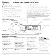
Measurementcategories(Over-voltagecategories)
Toensuresafeoperationofmeasuringinstruments,IEC61010establishessafety
standards for various electrical environments, categorized as O to CAT IV, and
calledmeasurementcategories.
Higher-numbered categories correspond to electrical environments with greater
momentary energy, so a measuring instrument designed for CAT III environments
canenduregreatermomentaryenergythanonedesignedforCATII.
O: Circuitswhicharenotdirectlyconnectedtothemainspowersupply.
CATII: Primary electrical circuits of equipment connectedto an AC electrical
CATIII: Primary electrical circuits of the equipment connected directly to the
distributionpanel,andfeedersfromthedistributionpaneltooutlets.
CATIV: The circuit from the service drop to the serviceentrance, and to the
power meter and primary overcurrent protection device (distribution
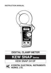
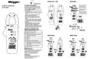
DigitalclamptesterforACleakagecurrentmeasurement.
Least affected by external magnetic field, providing wide measuring
rangefromverysmalltolargecurrents.
Designed to safety standard IEC 61010-2-032: measurement CAT.
300Vandpollutiondegree2.
Data hold function toallow for easy readings in dimly lit or hard-to-
Providesfilteringfunctiontoremovehighfrequencygeneratedbysuch
Sleepfunctionpreventsunnecessarypowerconsumption.
Dynamicrangeof4000countsfullscale.
Largeeasy-to-readLCDdisplaywithletterheightof13mm.
Transformerjawsfittedwithguardtofurtherimprovesafety.
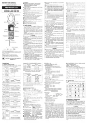
Measuringrangesandaccuracy
Range MeasuringRange Accuracy(Frequencyrange)
When measuring current which pulse element is superposed, differences of the
indicatedvalue maybecau sed between ranges, if the peak value exceeds the
measurement range to a large extent. In thiscase, the reading at the bigger
rangeshouldbetakenasarightvalue.
Sensitive transformer jaws are used for Leakage clam p meter.B ecause of t he
characteristic s of trans form er ja ws, whi ch ca n be o pen ed an d clos ed, it is
impossibletoeliminate theinterferen ceof external magnetic fieldco mpletely.If
there are something, which genera ting large magnetic f ield, at a nearb y site,
current valuecan be displayed (
cannot be displayed.) before clampingo n
theconductor.Forsuchacase,pleaseusetheinstrumentatalocationfarfrom
thething,whichgeneratingmagneticfield.
Followingarethetypicalthingsgeneratingmagneticfield.
Conductor fed large current, Motor, Equipment which has magnet, Integrating
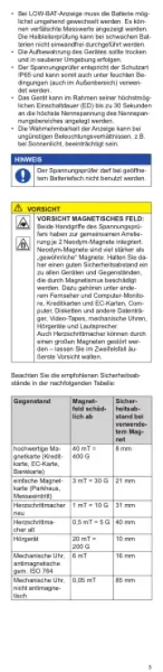
Liquid crystal display with maximum reading of
"BATT"markappearsonthedisplay
"OL"appearson thedisplaywhenupperlimit of
measuringrangeisexceeded
Approx.2.5timespersecond
Indooruse,Altitudeupto2000m
,relativehumidity85%orless
,relativehumidity85%orless
(withoutcondensation)
,relativehumidity85%orless
(withoutcondensation)
Two1.5VR03(UM-4)batteries
Automatically powered down in about 10
minutesafterthelastswitchoperation
IEC61010-1,IEC61010-2-032
300V, pollution degree 2
IEC61326(EMC),EN50581(RoHS)
120Armsmax.for10seconds
3470Vrms (50/60Hz) for 5 seconds between
metalpart oftransformerjaws andhousing case
(excepttransformerjawcase)
or greaterat1000Vbetweenmetal part
of transformer jaws and housing case (except
Approx.28mmindiametermax.
Approx.220gincludingbatteries
TwoR03(UM-4)batteries
CarryingcaseModel9097
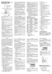
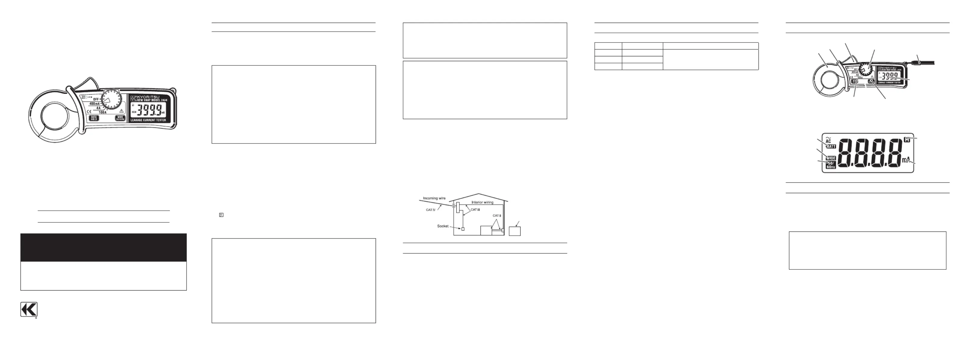
5. PREPARATIONS FOR MEASUREMENT
5-1 Checking Battery Voltage
Set the Range Selector Switch to any position other than the OFF
position. If the marks on the display is clearly visible without "BATT"
markshowing, battery voltageis OK.Ifthe displayblanks or"BATT"is
indicated, replace the batteries according to section 8: Battery
When the instrument is left powered on, the Sleep function
automaticallyshut the poweroff;The displayblanks evenifthe
RangeSelector Switch is set to a position other than the OFF
positioninthisstate.Topowerontheinstrument,turntheRange
SelectorSwitchorpressanybutton.Ifthedisplaystillblanks,the
batteriesarecompletelyexhausted.Replacethebatteries.
5-2 Checking Switch Setting
Make sure that the Range Selector Switch is set to the appropriate
Alsomakesure that datahold functionisnotenabled. Ifinappropriate
rangeisselected,desiredmeasurementcannotbemade.
Frequency Selector Button
Barrier is a part providing protection against electrical shock and
ensuring the minimum required air and creepage distances.