No: 341385 10/23
radiant
®
LED Dimmer, 2-Wire. LED: 1.25A (150W)
Gradateur à DEL radiant
®
à deux ls. DEL : 1,25 A (150 W)
Regulador LED radiant® de 2 cables. LED: 1,25 A (150 W)
Installation Instructions • Notice d’Installation • Instrucciones de Instalación
Catalog Number(s) • Numéro(s) de Catalogue • Les Numéros de Catalogue: RHL153P
RATINGS
Voltage: 120VAC, 60Hz
Dimmable LED Loads: 1.25A (150W), Forward Phase Dimming Only
Dimmable CFL/Incandescent/Halogen Loads: 150W
NEMA SSL-7A Compliant
IMPORTANT NOTES
1. All dimmers can be damaged by improper wiring. Check for short circuits
prior to installing the dimmer with a lamp load in the circuit.
Procedure for short circuit check:
a. Disconnect power to circuit by removing fuse or turn circuit breakers
OFF.
b. Install a switch instead of the dimmer. Turn the switch to the ON
position.
c. Turn power ON. If the circuit breaker trips, a short circuit is present.
If the light fails to turn ON and OFF with the switch, the wiring may
be incorrect.
d. Correct wiring, if necessary, and retest.
e. Install the dimmer only after the light operates properly with the switch.
2. Protect this product from dust and dirt. The dimmer can be damaged by
contaminates encountered during the construction process. If lighting
is required prior to the construction process completion, then a switch
should be temporarily installed in place of this product. This product
should not be installed until the construction process is complete.
Any dimmer damage due to improper installation is not covered under
warranty.
DIRECTIONS
1. Disconnect power to circuit by removing fuse or turn the circuit breakers
Off before installing.
2. Remove wall plate and switch mounting screws, pull existing switch from
wall box.
3. Disconnect existing switch from circuit. For 3-way installations: Identify
the “Common” wire (wire connected to the terminal marked common
or odd colored terminal). For new installation identify wire connected to
power source or load.
4. Connect dimmer as shown in the installation diagram using #12 or #14
AWG wire stranded or solid copper conductors. Note that the dimmer
and 3-way switch positions may also be reversed from that shown.
Strip the wire to the length shown on the back of the product. (Figure 2
or Figure 3)
5. Install product in wall box, with the word “Top” on the strap right side up,
using mounting screws provided.
6. Attach wall plate and then restore power to the unit.
7. Calibration of low end dimming limit may be required to optimize
performance. To adjust, remove wall plate and follow steps as shown
under “Min Level Trim” in the USER ADJUSTMENTS section. Note:
many LED models are only designed to dim to 5-10% brightness levels.
8. Burst mode – as shown in the USER ADJUSTMENT section – is an
optional setting to use if slow or delayed startups of the light(s) exist
when switched on. Leaving dimmer in high, med, or low burst may help
to eliminate problem.
9. Optional soft start feature (fade-to-on) may be enabled as described in
the USER ADJUSTMENTS section.
10. If any adjustments produce unsatisfactory results, the dimmer can be
reset to factory default, and start again at Step 7 above.
ANGING OF DIMMERS AND OTHER DEVICES
MULTIPLE GANGING OF DIMMERS AND OTHER DEVICES
NOTE: It is normal for the dimmer to feel warm during operation. Use a
separate neutral wire for each phase of a multiphase system containing a
dimmer, and for high power single phase applications where ickering is
present.
Any combination of dimmer models and other devices may be ganged
together. No derating of the dimmer is required. The maximum load for this
product based on the compatible load types are:
• 1.25A (150 Watts) for Light Emitting Diode (LED)
• 150 Watts for Incandescent and Halogen
DIMMER OPERATION
Paddle Switch
• Toggling the Paddle Switch up and
down switches the dimmer’s Hot
terminal between the two traveler
terminals, cycling the load power on
and off.
• The switch operates in both single-
pole and three-way installations.
Dimming Slider
• Sliding to the top-most position
sends full power to the load resulting
in maximum brightness.
• Sliding to the bottom-most position
produces minimum brightness
(maximum dimming).
Calibration Button
• Use to set Min Trim, Max Trim, and
Burst Level.
USER ADJUSTMENTS
If needed, follow instructions below to optimize low/high end dimming limits,
remove icker at either end, and eliminate startup delays. Note: power to
the circuit should be on, with the ground wire lead connected.
Min Level Trim (Sets min brightness higher or lower than default)
1. With the dimmer switch ON: set
the slider all the way down.
2. Push and hold the CAL button.
Light will go to its lowest setting
3. While still holding the CAL
button: move slider upward
until the load is illuminated.
Then adjust up/down until
desired low end dimming limit is
reached by viewing light intensity.
4. Release the CAL button. Load
Light(s) will ash to indicate Min
level is set and stored.
Note: Move slider back to bottom position to view new Min dim level.
Repeat as desired to re-adjust or cut out icker from dim range.
Max Level Trim (Energy saver, reduces max brightness)
a). With the dimmer switch ON: set
the slider all the way up.
b). Push and hold the CAL button.
Light will go to its highest
setting
c). While still holding the CAL
button: move slider downward
until desired high end dimming
limit is reached by viewing light
intensity.
d). Release the CAL button. Load
Light(s) will ash to indicate Max
level is set and stored.
Note: Move slider back to top position to view new Max dim level.
Repeat as desired to re-adjust or cut out icker from dim range.
Burst Mode (Reduce/eliminate delayed turn-ons, multiple lights not
starting at the same time)
I. With the dimmer switch ON: set
the slider to the center.
II. Tap the CAL button once to enter
Burst Mode setup (lights will turn
off). Tap a second time to set to
High Burst. Each press of the
CAL button will cycle through
burst settings as shown below
(lights will change intensity).
Enters
Burst
Setup
High
Burst
Med
Burst
Low
Burst O
Repeats
to High
1
Tap
2
Taps
3
Taps
4
Taps
5
Taps
6
Taps
III. After desired burst has been selected,
move slider away from center to
exit. Lights will ash to indicate burst
setting has been saved.
Reset to Factory Default (resets Min, Max, and Burst to default)
• Slider can be in any position, push and hold the CAL button for
approximately 8 seconds. Load light(s) will ash to indicate reset.
Release the CAL button. Any desired setting (Low Trim, High Trim,
or Burst) will need to be performed if desired.
Due to ongoing product improvements, Legrand reserves
the right to change specications without notice. For the
most recent instruction sheets or more information on this
product, please see this link or scan the QR code:
https://legrand.us/p/rhl153p
Enable Soft Start (Lights Fade-to-On, User Preference)
*With the dimmer switch OFF: set the slider all the way up. Press and hold
the CAL button, then switch the dimmer paddle to ON position. Lights will
ash indicating soft start feature saved.
READ AND SAVE THESE INSTRUCTIONS
To be installed by a certied electrician or other qualied person.
WARNING – To prevent severe shock or electrocution, always turn power off
at the service panel before installing this product, working on the circuit, or
changing a lamp.
CAUTION
• Do not use this product to control a receptacle, a motor operated appliance,
or a transformer based appliance.
• Do not use this product with loads whose combined power requirements
exceed the maximum power rating (stated in watts, amperes, or volt-
amperes) of the dimmer.
• A 3 watt minimum load is required.
• Use only with dimmable LED, CFL, or Incandescent loads (bulb/xture test
list at www.legrand.us)
• Do not connect this product to a power source other than 120VAC, 60Hz.
• Use copper wire only.
NEMA SSL-7A-2015/NEMA-77-2015
LIRE ET CONSERVER CES INSTRUCTIONS
Doit être installé par un électricien certié ou une autre personne qualiée.
AVERTISSEMENT : an d’éviter tout choc électrique ou électrocution grave,
toujours éteindre l’alimentation sur le panneau de service avant d’installer ce
produit, de travailler sur le circuit ou de changer une lampe.
ATTENTION
• Ne pas utiliser ce produit pour contrôler une prise de courant, un appareil à
moteur ou un appareil à transformateur.
• Ne pas utiliser ce produit avec des charges dont la puissance combinée
dépasse la puissance nominale maximale (indiquée en watts, ampères ou
volts-ampères) du gradateur.
• Une ampoule d’au moins 3 watts est requise.
• A utiliser uniquement avec des charges DEL, CFL ou incandescentes
à gradation (liste de tests d’ampoules et de luminaires sur le site www.
legrand.us).
• Ne brancher ce produit qu’à une source d’alimentation de 120 VCA, 60 Hz.
• N’utiliser que des ls en cuivre.
NEMA SSL-7A-2015/NEMA-77-2015
LEA Y CONSERVE ESTAS INSTRUCCIONES
Para ser instalado por un electricista certicado o persona competente.
ADVERTENCIA – Para evitar una fuerte descarga eléctrica o electrocución,
siempre apague el suministro de energía desde el panel de servicio antes
de instalar esta unidad, cuando esté trabajando en el circuito o cambiando
una bombilla.
PRECAUCIÓN
• No utilice este producto para controlar un receptáculo, un dispositivo a
motor ni un dispositivo con transformador.
• No utilice este producto con cargas cuyos requisitos de potencia
combinados excedan la potencia máxima (indicada en vatios, amperios o
voltios-amperios) del regulador.
• Se requiere una carga mínima de 3 vatios.
• Utilícelo solo con cargas LED, CFL o incandescentes regulables (encontrará
una lista de prueba de bombillas/luminarias en www.legrand.us).
• No conecte este producto a un suministro eléctrico que no sea de 120
VCA, 60 Hz.
• Utilice únicamente cable de cobre.
NEMA SSL-7A-2015/NEMA-77-2015
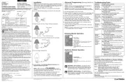
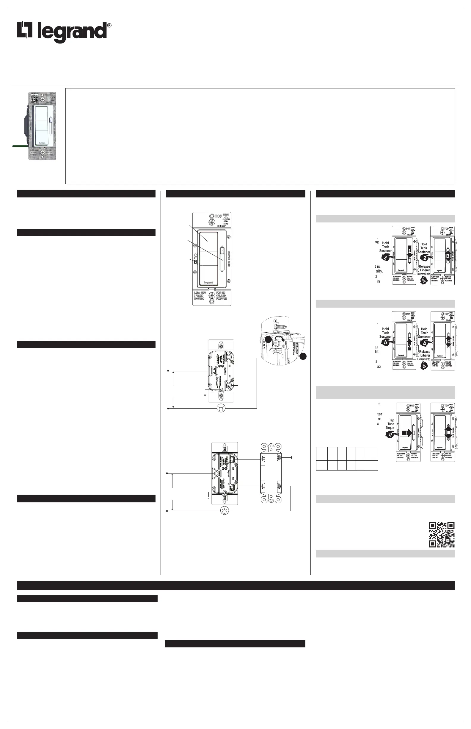
RHL153P
Figure 1 / Figure 1 / Figura 1
Paddle/
Palette/
Paleta
Slider/
Glissière/
Control
deslizante
Calibration/
Étalonnage/
Calibración
Hot (Black)
Chaud (Noir)
Caliente (Negro)
Neutral (White)
Neutre (Blanc)
Neutro (Blanco)
Ground
Fil de Terre
Alambre de tierra
DIMMER
GRADATEUR
ATENUADOR
120VAC 60 Hz
120VCA 60 Hz
120VAC 60 Hz
Do not wire this
terminal
Ne pas raccorder
cette borne
No cablear este
borne
Load
Charge
Carga
Traveler Wire to
3-Way Switch
Commun vers
interrupteur
3 voies
3-Way Switch
Interrupteur 3 voies
Interruptor de 3 vías
Alambre
comúm hacia
interruptor
de 3 vías
Alambre
comúm hacia
interruptor
de 3 vías
Hot (Black)
Chaud (Noir)
Caliente (Negro)
Neutral (White)
Neutre (Blanc)
Neutro (Blanco)
Load
Charge
Carga
Traveler Wire to
3-Way Switch
Commun vers
interrupteur
3 voies
Ground
Fil de Terre
Alambre de tierra
Ground
Fil de Terre
Alambre de tierra
DIMMER
GRADATEUR
ATENUADOR
120VAC 60 Hz
120VCA 60 Hz
120VAC 60 Hz
3-Way / 3 voies / 3 vías
Figure 3 / Figure 3 / Figura 3
Single Pole / Unipolaire / Unipolar
Figure 2 / Figure 2 / Figura 2
Terminal Screw Torque: /
Vis de borne Couple: /
Tornillo de terminales
Par motor:
14-16 lbf-in
#12 or #14AWG
1
2
INSTRUCTIONS EN FRANÇAIS
CLASSEMENTS
Tension : 120 V CA, 60 Hz
Charges DEL à gradation : 1,25 A (150 W), gradation en phase avant
uniquement
Charges à gradation CFL/Incandescent/Halogène : 150 W
Conforme à la norme NEMA SSL-7A
REMARQUES IMPORTANTES
1. Tous les gradateurs peuvent être endommagés par un mauvais câblage.
Vériez qu’il n’y a pas de court-circuit avant d’installer le gradateur avec
une charge de lampe dans le circuit.
Procédure de vérication de court-circuit :
a. Coupez l’alimentation du circuit en retirant le fusible ou en mettant les
disjoncteurs en position d’arrêt.
b. Installez un interrupteur au lieu d’un gradateur. Mettez l’interrupteur en
position de marche.
c. Mettez l’appareil sous tension. Si le disjoncteur se déclenche, il y a
un court-circuit. Si le voyant ne s’allume pas et ne s’éteint pas avec
l’interrupteur, il se peut que le câblage soit incorrect.
d. Corrigez le câblage si nécessaire, et refaites un essai.
e. N’installez le gradateur qu’une fois que le voyant fonctionne
correctement avec l’interrupteur.
2. Protégez ce produit de la poussière et de la saleté. Le gradateur
peut être endommagé par des contaminants rencontrés au cours
du processus de construction. Si un éclairage est nécessaire avant
l’achèvement du processus de construction, un interrupteur doit être
installé temporairement à la place de ce produit. Ce produit ne doit pas
être installé avant la n du processus de construction.
Tout dommage causé par une mauvaise installation n’est pas couvert
par la garantie.
DIRECTIONS
1. Avant l’installation, coupez l’alimentation du circuit en retirant le fusible ou
en mettant les disjoncteurs en position d’arrêt.
2. Retirez la plaque murale et les vis de montage de l’interrupteur, puis
enlevez l’interrupteur existant de la boîte d’applique.
3. Déconnectez l’interrupteur existant du circuit. Pour les installations à
trois voies : Identiez le l « commun » (l connecté à la borne marquée
« commun » ou à la borne de couleur singulière). Dans le cas d’une
nouvelle installation, identiez le l connecté à la source d’alimentation
ou à la charge.
4. Raccordez le gradateur comme il est indiqué dans le schéma
d’installation, en utilisant des conducteurs en cuivre massif ou câblé de
calibre 12 ou 14. Notez que les positions du gradateur et de l’interrupteur
à trois voies peuvent également être inversées par rapport à l’illustration.
Dénudez le l à la longueur indiquée au dos du produit. (Figure 2 ou
Figure 3)
5. Installez le produit dans la boîte d’applique, avec le mot « Top » (Haut)
sur la sangle à l’endroit, en utilisant les vis de montage fournies.
6. Fixez la plaque murale et rétablissez l’alimentation de l’appareil.
7. L’étalonnage de la limite inférieure de gradation peut être
nécessaire pour optimiser les performances. Pour le régler, retirez la
plaque murale et suivez les étapes indiquées sous « Niveau de spectre
min. » dans la section « RÉGLAGES UTILISATEURS ». Remarque : de
nombreux modèles de DEL ne sont conçus que pour une gradation de 5
à 10 % de la luminosité.
8. Le mode rafale - comme indiqué dans la section RÉGLAGES
UTILISATEURS - est un réglage optionnel à utiliser en cas de
démarrage lent ou retardé de la (des) lampe(s) à l’allumage. Laisser
le gradateur en mode faible, moyen ou élevé peut aider à éliminer le
problème
9. La fonction optionnelle de démarrage progressif (allumage graduel) peut
être activée comme décrit dans la section RÉGLAGES UTILISATEURS.
10.Si l’un des ajustements ne donne pas de résultats satisfaisants, le
gradateur peut être réinitialisé aux paramètres d’usine par défaut, et il
faut recommencer à l’étape 7 ci-dessus.
Note: High Burst Mode is
recommended for best results.
Med or low can be used if lights
visibly ash when switched on in
high burst setting.