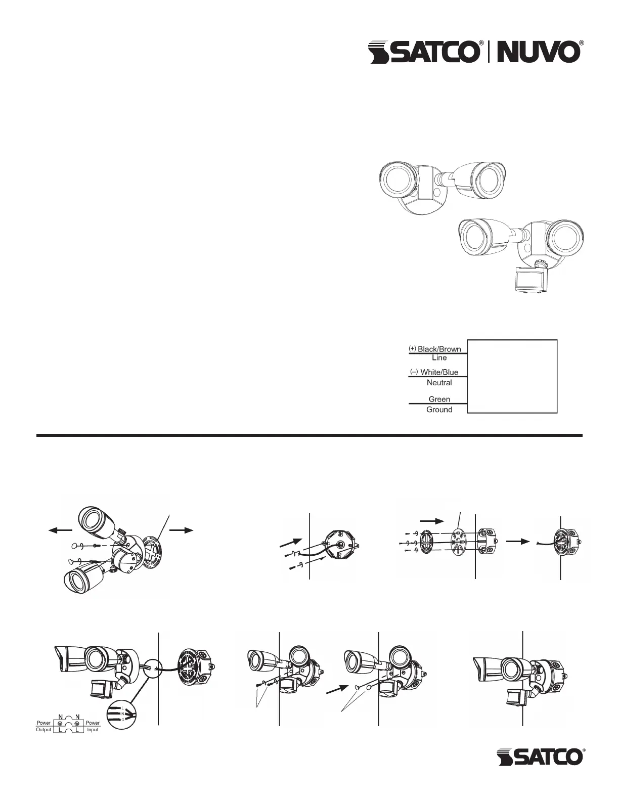
(2) Plastic
Plugs
Mounting
Plate
Gasket
STEP 1: Disconnect power supply.
Remove (2) plastic plugs. Remove
inserted screws and mounting plate.
STEP 2: Attach junction box on
the wall (not supplied).
STEP 3: Fix mounting plate
and gasket onto junction box.
LED DUAL HEAD
SECURITY LIGHT
Models: 65/710, 65/712, 65/714, 65/716, 65/718, 65/720
Models with Optional Motion Sensor: 65/711, 65/713, 65/715, 65/717, 65/719, 65/721
INSTALLATION: Wall Mount (External Junction Box)
INSTALLATION AND SAFETY INSTRUCTIONS
IMPORTANT: Read before installing xture. Retain for future reference.
1
Satco Products, Inc.
Brent wood, NY 11717© Copyright 2020 Satco Products, Inc. 8/20
Optional
Motion Sensor
Fixture
WIRING DIAGRAM
(2) M5*18
Screws
STEP 4: Connect the wires, refer
to the Wiring Diagram.
STEP 5: Secure xture onto mounting
plate with screws, replace plastic plugs.
STEP 6: Check xture and
connect power supply.
WARNING: Risk of Fire or Electric Shock
• Commercial installation, service and maintenance of luminaries should be
performed by a qualied licensed electrician. If you are unsure about the
installation or maintenance of the luminaries, consult a qualied licensed
electrician and check your local electrical code.
• Turn OFF power at fuse or circuit breaker before wiring xture to power supply.
• Turn OFF power when you perform any maintenance.
• Verify that supply voltage is correct by comparing it with the luminaire label.
• Risk of Burn. Disconnect power and allow xture to cool before handling.
• Clean glass lens with non-abrasive glass cleaning solution.
• Do not open xture to clean the LED. Do not touch the LED.
WIRING: If wiring does not include a ground wire, consult your local electrical
code for approved grounding methods. For proper connection, place wire nut
over wires and twist clockwise until tight.
1. Connect supply wires. Use wire nut to connect the black xture wire to the
black power supply wire and the white xture wire to the white (neutral) supply
wire. NOTE: Lamp heads must be positioned above motion sensor head and
controls on motion sensor must face the ground.
2. Aim lamp heads and install optional visors. Loosen knobs and aim lamp heads.
CAUTION: Risk of Shock: Aim lamp heads at least 20º down below horizontal
in order to prevent water from accumulating inside lens. After lamp heads are
positioned as desired, align the optional visor over the front of the lamp head
and secure by tightening set screw on visor.
3. Weatherproof gaskets and junction box with silicone sealant, tighten all screws.


