LiftMaster 850LMC Manual
LiftMaster
Ikke kategoriseret
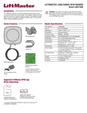
850LMC

| Mærke: | LiftMaster |
| Kategori: | Ikke kategoriseret |
| Model: | 850LMC |
Har du brug for hjælp?
Hvis du har brug for hjælp til LiftMaster 850LMC stil et spørgsmål nedenfor, og andre brugere vil svare dig
Ikke kategoriseret LiftMaster Manualer

8 August 2025
7 August 2025
7 August 2025

7 August 2025
7 August 2025
7 August 2025

15 Juni 2025
4 September 2024

3 September 2024
3 September 2024
Ikke kategoriseret Manualer
- Lelit
- Pulse Eight
- Jamo
- Doona
- CLIMAQUA
- Drawmer
- Triax
- NGS
- Celestion
- Foscam
- Orangemonkie
- Chandler
- Emporia
- Moki
- Crest Audio
Nyeste Ikke kategoriseret Manualer

2 November 2025

2 November 2025

2 November 2025

2 November 2025

2 November 2025

2 November 2025

2 November 2025

2 November 2025

2 November 2025

2 November 2025