Lincoln Electric CHAMELEON 3V0 Manual
Lincoln Electric
Ikke kategoriseret
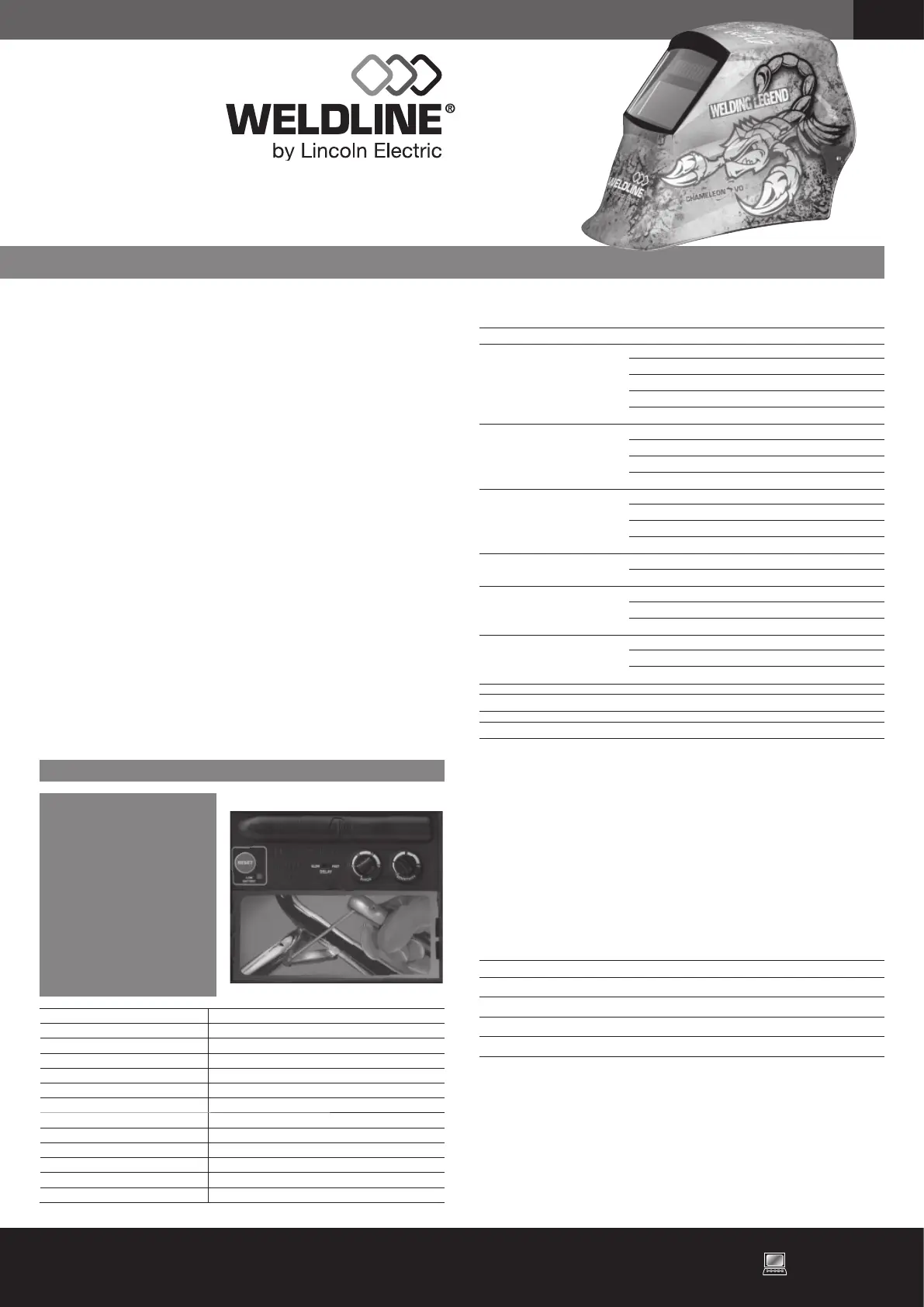
CHAMELEON 3V0
| Mærke: | Lincoln Electric |
| Kategori: | Ikke kategoriseret |
| Model: | CHAMELEON 3V0 |
Har du brug for hjælp?
Hvis du har brug for hjælp til Lincoln Electric CHAMELEON 3V0 stil et spørgsmål nedenfor, og andre brugere vil svare dig
Ikke kategoriseret Lincoln Electric Manualer

8 December 2025

8 December 2025

7 December 2025

7 December 2025

7 December 2025
24 September 2025
24 September 2025
24 September 2025
23 September 2025
23 September 2025
Ikke kategoriseret Manualer
- Anova
- Kopp
- Jane
- Kruidvat
- Fannova
- Challenge
- Victor Technology
- Heatfab
- Twisper
- Davis
- Redragon
- Hartke
- Narwal
- Integral LED
- Orbsmart
Nyeste Ikke kategoriseret Manualer

11 December 2025

11 December 2025

11 December 2025

11 December 2025

11 December 2025

11 December 2025

11 December 2025

11 December 2025

11 December 2025

11 December 2025