Livarno Lux 06019-IRF Manual


Læs gratis den danske manual til Livarno Lux 06019-IRF (5 sider) i kategorien Ikke kategoriseret. Denne vejledning er vurderet som hjælpsom af 5 personer og har en gennemsnitlig bedømmelse på 4.6 stjerner ud af 3 anmeldelser. Har du et spørgsmål om Livarno Lux 06019-IRF, eller vil du spørge andre brugere om produktet?

Side 1/5
TELESKOP-INSEKTENSCHUTZ-
FENSTER / EXTENDABLE INSECT
SCREEN / MOUSTIQUAIRE
TÉLÉSCOPIQUE POUR FENÊTRE
TELESKOP-INSEKTEN -
SCHUTZFENSTER
Montageanleitung und Sicherheitsheinweise
TELESKOPVINDUE MED
INSEKTNET
Monteringsvejledning og sikkerhedsanvisninger
MOSQUITERA EXTENSIBLE
PARA VENTANA
Manual de instrucciones e indicaciones
de seguridad
EXTENDABLE INSECT SCREEN
Assembly, operating and safety instructions
IAN 383937_2107
MOUSTIQUAIRE TÉLÉSCOPIQUE
POUR FENÊTRE
Notice de montage et consignes de sécurité
TELESCOPISCHE INSECTENHOR
VOOR HET RAAM
Montagehandleiding en veiligheidsinstructies
TELESKOPICKÁ SIEŤKA PROTI
HMYZU
Montážny návod a bezpečnostné upozornenia
OCHRANA PROTI HMYZU
NA OKNO
Návod k montáži a bezpečnostní upozornění
TELESKOPOWA OSŁONA PRZED
OWADAMI NA OKNO
Instrukcja montażu i wskazówki bezpieczeństwa
DE/AT/CH DE/AT/CH DE/AT/CH DE/AT/CH DE/AT/CH DE/AT/CH DE/AT/CH DE/AT/CH DE/AT/CH DE/AT/CH DE/AT/CH DE/AT/CH V2.0
Tritt innerhalb von 3 Jahren ab dem Kauf-
datum dieses Produkts ein Material- oder
Fabrikationsfehler auf, wird das Produkt
von uns – nach unserer Wahl – für Sie
kostenlos repariert oder ersetzt. Diese
Garantie verfällt, wenn das Produkt be-
schädigt, nicht sachgemäß benutzt oder
gewartet wurde.
Die Garantieleistung gilt für Material-
oder Fabrikationsfehler. Diese Garantie
erstreckt sich nicht auf Produktteile, die
normaler Abnutzung ausgesetzt sind
(z. B. Batterien) und daher als Verschleiß-
teile angesehen werden können oder Be-
schädigungen an zerbrechlichen Teilen,
z. B. Schalter, Akkus oder die aus Glas
gefertigt sind.
Service
Bei Fragen oder Reklamationen schreiben
Sie uns bitte eine E-Mail an die unten an-
gegebene E-Mail-adresse:
g.kundenservice@gmx.at
IAN 383937_2107
Bitte geben Sie Ihre IAN-Nummer an.
Informationen
Inverkehrbringer
Goldner GmbH
Ringstrasse 24
6830 Rankweil
ÖSTERREICH
Verfahren Sie beim linken Seitenprofil
2
, beim unteren Querprofil
6
, und
beim oberen Querprofil
7
genauso.
Die weitere Demontage erfolgt sinn-
gemäß in umgekehrter Reihenfolge.
Lagern Sie das Produkt nach der
Demontage trocken.
Reinigung
Verwenden Sie keinesfalls ätzende
oder scheuernde Reinigungsmittel.
Reinigen Sie das Insektenschutzge-
webe und die Profile mit einem
schwach eingestellten Handstaub-
sauger (schwächste Stufe).
Verwenden Sie ggf. ein mildes
Reinigungsmittel.
Wartung
Das Produkt ist wartungsfrei. Es kann
ganzjährig am Fenster verbaut bleiben.
Die Gasdruckfeder bzw. die Federspan-
nung bedürfen ebenfalls keiner Wartung
und keiner Kontrolle.
Entsorgung
Werfen Sie das Produkt nicht in den Haus-
müll. Erkundigen Sie sich in Ihrer Stadt
oder Gemeinde nach einer entsprechend
umwelt- und sachgerechten Entsorgung.
Die Verpackung besteht aus umweltfreund-
lichen Materialien, die Sie über die örtli-
chen Recyclingstellen entsorgen können.
Garantie
Das Produkt wurde nach strengen Qualitäts-
richtlinien sorgfältig produziert und vor
Anlieferung gewissenhaft geprüft. Im Falle
von Mängeln dieses Produkts stehen Ihnen
gegen den Verkäufer des Produkts ge-
setzliche Rechte zu. Diese gesetzlichen
Rechte werden durch unsere im Folgenden
dargestellte Garantie nicht eingeschränkt.
Sie erhalten auf dieses Produkt 3 Jahre
Garantie ab Kaufdatum. Die Garantiefrist
beginnt mit dem Kaufdatum. Bitte bewah-
ren Sie den Original-Kassenbon gut auf.
Diese Unterlage wird als Nachweis für
den Kauf benötigt.
Hinweis: Spannen Sie das Insekten-
schutzgewebe
7b
nicht zu straff. Es
sollte
n lediglich mögliche Falten ge-
glättet werden.
Drücken Sie anschließend die Schaum-
stoff-Randverstärkung wieder in das
jeweilige Profil ein. Nehmen Sie ggf.
eine zweite Person zur Hilfe.
Schritt 9
Schneiden Sie den Überstand am
Insektenschutzgewebe
7b
rechts,
links, oben und unten vorsichtig mit
einer Schere ab.
Hinweis: Schneiden Sie dabei nicht
versehentlich in das Insektenschutz-
gewebe
7b
. Die Schere zeigt dabei
immer in den Innenraum (s. Abb. H1).
Hinweis: Lassen Sie dabei 3 cm
mehr vom Insektenschutzgewebe als
Überstand und drücken Sie diesen
Überstand dann mit einem Löffelstiel
zwischen Profil und Schaumstoffrand-
verstärkung (s. Abb. H2).
Hinweis: Sollte bei der Montage des
oberen Querprofils
7
ein Spalt vorhan-
den sein, verwenden Sie das beigelegte
Klebeband
11
, um den Spalt zu schließen.
Dabei kleben Sie das Klebeband
11
im
Winkel entlang des Spaltes auf das obere
Querprol
7
in Verbindung mit der Innen-
seite des Fensterrahmen auf (s. Abb. I).
Sie haben das Produkt damit erfolgreich
montiert (s. Abb. J).
Demontage
Bitte beachten Sie, dass eine Wieder-
montage nicht möglich bzw. nicht vorge-
sehen ist. Falls Sie eine Wiedermontage
vornehmen möchten, beachten Sie, dass
Sie hierzu ein neues Insektenschutzge
webe
benötigen.
Führen Sie das kurze Ende des Innen-
sechskantschlüssels beim rechten
Seiten profil
1
oben oberhalb der
Schaumstoff-Randverstärkung (dick)
8
ein.
Ziehen Sie den Innensechskantschlüssel
anschließend soweit nach unten, bis
Sie die Schaumstoff-Randverstärkung
8
mit den Fingern aus dem rechten
Seitenprofil
1
vollständig herauszie-
hen können.
Hinweis: Schneiden Sie dabei nicht
versehentlich in das Insektenschutz-
gewebe
7b
.
Nehmen Sie die zweite Schaumstoff-
Randverstärkung
8
zur Hand und
verfahren Sie auf der linken Seite
genauso.
Hinweis: Spannen Sie das Insekten-
schutzgewebe
7b
nicht zu straff. Es
sollten lediglich mögliche Falten ge-
glättet werden. Wenn Sie das Insek-
tenschutzgewebe
7b
zu straff spannen,
können sich die Schaumstoff-Randver-
stärkungen
8
aus den Seitenprofilen
1
,
2
lösen und dadurch auch das
Insektenschutzgewebe
7b
.
Schritt 8 (Insektenschutzgewebe
unten einspannen)
Beginnen Sie nun beim unteren Quer-
profil
6
rechts, die Schaumstoff-Rand-
verstärkung (dünn)
10
zusammen mit
dem Insektenschutzgewebe
7b
ein-
zuspannen (s. Abb. G).
Umschlagen Sie die Schaumstoff-Rand-
verstärkung
10
mit dem Insektenschutz-
gewebe
7b
und drücken Sie diese
zusammen in das untere Querprofil
6
ein. Halten Sie dazu das Insekten-
schutzgewebe
7b
etwas unter Span-
nung. Nehmen Sie dazu ggf. eine
zweite Person zur Hilfe.
Beachten Sie, dass bei den Profilüber-
gängen des unteren Querprofils
6
das Insektenschutzgewebe
7b
nicht zu
stark gespannt wird, da dieses sonst
einreißen könnte.
Den Überstand der Schaumstoff-Rand-
verstärkung
10
können Sie vorsichtig
mit einer Schere kürzen.
Hinweis: Schneiden Sie dabei nicht
versehentlich in das Insektenschutz-
gewebe
7b
.
Hinweis: Die Schaumstoff-Randver-
stärkung
9
,
10
darf nicht über die
Ecke eingespannt werden.
Nachspannen:
Gehen Sie wie folgt vor, falls das Insekten-
schutzgewebe
7b
nochmals nachgespannt
werden soll (z. B. bei Falten im Insekten-
schutzgewebe
7b
):
Z
iehen Sie an der Stelle mit den Falten
den Überstand am Insektenschutzge-
webe
7b
langsam und vorsichtig heraus
,
bis sich die Schaumstoff-Randverstär-
kung löst. Nun können Sie das Insek-
tenschutzgewebe
7b
nachspannen
(s. Abb. H).
an. Nutzen Sie dafür den beigelegten
Innensechskantschlüssel.
Hinweis: Überdrehen Sie dabei die
Schrauben nicht, da sich das Quer-
profil
7
sonst verformen kann.
Schritt 6 (Insektenschutzgewebe
oben einspannen)
Hinweis: Der obere mittlere Teil des
Insektenschutzgewebes
7b
ist bereits mit
einer Schaumstoff-Randverstärkung im
oberen Querprofil
7
mittig vormontiert.
Schneiden Sie ein Stück Schaumstoff-
Randverstärkung (dünn)
9
zurecht.
Hierfür messen Sie den Abstand von
Außenkante Querprofil
7
von der
rechten Seite bis zur vormontierten
Schaumstoff-Randverstärkung (s. Abb. E).
Um das restliche Insektengewebe im
oberen Querprofil auf der rechten
Seite zu fixieren, nehmen Sie das
zurechtgeschnittene Stück Schaum-
stoff-Randverstärkung
9
zur Hand.
Umschlagen Sie diese mit dem Insek-
tenschutzgewebe
7b
.
Drücken Sie nun das zurechtgeschnit-
tene Stück Schaumstoff-Randverstär-
kung
9
zusammen mit dem
Insektenschutzgewebe
7b
entlang
der noch nicht vormontierten Stelle
des oberen Querprofils
7
auf der
rechten Seite ein (s. Abb. E1).
Verfahren Sie auf der linken Seite
des oberen Querprofils
7
genauso.
Hinweis: Nehmen Sie dazu ggf.
eine zweite Person zur Hilfe.
Hinweis: Schneiden Sie dabei nicht
versehentlich in das Insektenschutz-
gewebe
7b
(s. Abb. E).
Schritt 7 (Insektenschutzgewebe
in die Seitenprofile einspannen)
Beginnen Sie nun beim rechten Seiten-
profil
1
oben, die Schaumstoff-Rand-
verstärkung (dick)
8
zusammen mit
dem Insektenschutzgewebe
7b
ein-
zuspannen (s. Abb. F).
Umschlagen Sie die Schaumstoff-Rand-
verstärkung
8
mit dem Insekten-
schutzgewebe
7b
und drücken Sie
diese zusammen in das rechte Seiten-
profil
1
ein. Halten Sie dazu das In-
sektenschutzgewebe
7b
etwas unter
Spannung. Nehmen Sie dazu ggf.
eine zweite Person zur Hilfe.
Den Überstand der Schaumstoff-Rand-
verstärkung
8
können Sie vorsichtig
mit einer Schere kürzen.
Achten Sie darauf, dass die Seiten-
profile
1
2
rechts und links ohne
Spalt bündig am Fensterrahmen an-
liegen (ggf. etwas nachschieben).
Schritt 4
Ziehen Sie das untere Querprofil
6
so weit auseinander (s. Abb. C), bis
es seitlich mit den beiden Seitenprofi-
len
1
2
rechts und links bündig ist
(s. Abb. C1). Sie müssen es auf die
Fortsätze an den beiden Seitenprofi-
len
1
2
rechts und links einschieben
können (s. Abb. C1).
Achten Sie darauf, dass die Bürsten-
dichtung
6a
nach unten in den Innen-
raum zeigt (s. Abb. C).
Damit das untere Querprofil
6
in der
Breite fixiert werden kann, schieben
Sie die Fixierplatten in der Mitte des
unteren Querprofils
6
jeweils bis
zum Anschlag nach rechts und links.
Fixieren Sie anschließend die Fixier-
platten. Ziehen Sie dafür die zwei
Schrauben handfest im Uhrzeigersinn
an. Nutzen Sie dafür den beigelegten
Innensechskantschlüssel (s. Abb. C2).
Hinweis: Überdrehen Sie dabei die
Schrauben nicht, da sich das Quer-
profil
6
sonst verformen kann.
Schritt 5
Rollen Sie das Insektenschutzgewebe
7b
vom oberen Querprofil
7
ab.
Hinweis: Der obere mittlere Teil des
Insektenschutzgewebes
7b
ist bereits
mit einer Schaumstoff-Randverstärkung
im oberen Querprofil
7
mittig vor-
montiert.
Ziehen Sie das obere Querprofil
7
so weit auseinander (s. Abb. D), bis
es seitlich mit den beiden Seitenprofi-
len
1
,
2
rechts und links bündig ist.
Sie müssen es auf die Fortsätze an
den beiden Seitenprofilen
1
,
2
rechts und links einschieben können
(s. Abb. D).
Achten Sie darauf, dass die Bürsten-
dichtung
7a
nach oben in den Innen-
raum zeigt (s. Abb. D).
Damit das obere Querprofil
7
in der
Breite fixiert werden kann, schieben
Sie die Fixierplatten in der Mitte des
oberen Querprofils
7
jeweils bis
zum Anschlag nach rechts und links
(s. Abb. D1).
Fixieren Sie anschließend die Fixier-
platten. Ziehen Sie dafür die zwei
Schrauben handfest im Uhrzeigersinn
dass das Gleitstück
4
im auszuzie-
henden Seitenprofil
1
fixiert wird.
Verfahren Sie bei dem linken Seiten-
profil
2
genauso wie beim rechten
Seitenprofil
1
.
Hinweis: Das untere Metall-Gleit
stück
mit Kreuzschlitzschrauben darf nicht
gelöst werden.
Schritt 2b (Fensterrahmenhöhe
von 95‒150 cm)
Halten Sie das rechte Seitenprofil
1
mit der Halteklammer
3
unten am
Fensterrahmen an (s. Abb. A2).
Hinweis: Die schwarze Gasdruck-
feder
5
im Inneren des Seitenprofils
1
muss sich oben am Fenster befinden.
Ziehen Sie das rechte Seitenprofil
1
oben 5 cm weiter aus, als Ihre tatsäch-
liche Fensterrahmenhöhe beträgt
(s. Abb. A3).
Fixieren Sie das Kunststoff-Gleitstück
4
im Inneren des rechten Seitenprofils
1
.
Ziehen Sie dafür die zwei Schrauben
handfest im Uhrzeigersinn an. Nutzen
Sie dafür den beigelegten Innensechs-
rundschlüssel (s. Abb. A1).
Hinweis: Überdrehen Sie die Schrau-
ben nicht, da sich das Seitenprofil
1
sonst verformen kann. Beachten Sie,
dass das Gleitstück
4
im auszuzie-
henden Seitenprofil
1
fixiert wird.
Verfahren Sie bei dem linken Seiten-
profil
2
genauso wie beim rechten
Seitenprofil
1
.
Hinweis: Das untere Metall-Gleit-
stück mit Kreuzschlitzschrauben darf
nicht gelöst werden.
Schritt 3
Hängen Sie das rechte Seitenprofil
1
mit der Halteklammer
3
unten am
Fensterrahmen ein (s. Abb. B).
Hinweis: Die schwarze Gasdruck-
feder
5
im Inneren des Seitenprofils
1
muss sich oben am Fenster befinden.
Drücken Sie das obere Ende des
rechten Seitenprofils
1
nach unten
(s. Abb. B1), bis Sie die Halteklammer
3
oben am Fensterrahmen einhänge
n
können (s. Abb. B2). Nehmen Sie
dazu Ihre zweite Hand zur Hilfe.
Durch langsames Entlasten fixiert sich
das rechte Seitenprofil
1
durch die
Gasdruckfeder
5
von selbst.
Verfahren Sie bei dem linken Seiten-
profil
2
genauso wie beim rechten
Seitenprofil
1
.
Gehen Sie vorsichtig mit
der Schere beim Kürzen des
Insektenschutzgewebes um
.
Vorbereitung
Benötigtes Werkzeug
und Material
Die genannten Werkzeuge und Materia-
lien sind nicht im Lieferumfang enthalten.
‒ Schere
‒ Maßband / Zollstock
Montage
Hinweis: Prüfen Sie vor der Montage den
äußeren Abstand zwischen Rollladen und
Fensterrahmen (Mindestabstand 1,5 cm).
Hinweis: Beginnen Sie mit der Montage
erst, wenn Sie sicher sind, dass alle Teile
vorhanden und unbeschädigt sind. Die
Teile
1
,
2
,
6
und
7
sind beschriftet.
Hinweis: Scannen Sie den folgenden
QR-Code für ein animiertes Montagevideo:
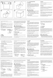
Schritt 1
Messen Sie Ihre Fensterrahmenhöhe
aus (s. Abb. A).
Schritt 2a (Fensterrahmenhöhe
von 90‒95 cm)
Schieben Sie das rechte Seitenprofil
1
bis zum Anschlag zusammen.
Fixieren Sie das Kunststoff-Gleitstück
4
im Inneren des rechten Seitenprofils
1
.
Ziehen Sie dafür die zwei Schrauben
handfest im Uhrzeigersinn an. Nutzen
Sie dafür den beigelegten Innensechs-
rundschlüssel (s. Abb. A1).
Hinweis: Überdrehen Sie die Schrau-
ben nicht, da sich das Seitenprofil
1
sonst verformen kann. Beachten Sie,
wenn sie beaufsichtigt oder
bezüglich des sicheren
Gebrauchs des Produkts
unterwiesen wurden und
die daraus resultierenden
Gefahren verstehen. Kin-
der dürfen nicht mit dem
Produkt spielen. Reinigung
und Benutzerwartung
dürfen nicht von Kindern
ohne Beaufsichtigung
durchgeführt werden.
Dieses Produkt darf nur
von einem Erwachsenen
angebracht werden.
LEBENSGEFAHR! Lehnen
Sie sich bei der Montage,
Demontage oder Reinigu
ng
nicht zu weit aus dem
Fenster.
Stellen Sie vor der Mon-
tage sicher, dass die Fläche
unterhalb Ihres Fensters für
die Zeit des Einbaus frei
von Gegenständen oder
Personen ist. Dadurch
vermeiden Sie mögliche
Schäden oder Verletzunge
n
durch herabfallende Teile.
VORSICHT! VERLET-
ZUNGSGEFAHR! Stel-
len Sie sicher, dass alle
Teile unbeschädigt und
sachgerecht montiert sind.
Bei unsachgemäßer Mon-
tage besteht Verletzungs-
gefahr. Beschädigte Teile
können die Sicherheit und
Funktion beeinflussen.
2 dünne Schaumstoff-Randverstärkung
(je 35 cm Länge)
2 dünne Schaumstoff-Randverstärkung
(je 65 cm Länge)
1 Innensechskantschlüssel
1 Innensechsrundschlüssel
1 Klebeband
4 Innensechskantschrauben (Ersatz)
1 Montageanleitung
Sicherheits-
hinweise
VOR GEBRAUCH BITTE DIE
MONTAGEANLEITUNG
LESEN! MONTAGEANLEI-
TUNG SORGFÄLTIG AUF-
BEWAHREN! HÄNDIGEN
SIE ALLE UNTERLAGEN BEI
WEITERGABE DES PRO-
DUKTES AN DRITTE EBEN-
FALLS MIT AUS.
LEBENS- UND UNFALL-
GEFAHR FÜR KLEIN-
KINDER UND KINDER!
Lassen Sie Kinder niemals
unbeaufsichtigt mit dem
Verpackungsmaterial und
dem Produkt. Es besteht
Erstickungsgefahr. Halten
Sie Kinder vom Produkt
fern.
Dieses Produkt kann von
Kindern ab 8 Jahren und
darüber sowie von Perso-
nen mit verringerten phy-
sischen, sensorischen oder
mentalen Fähigkeiten oder
Mangel an Erfahrung und
Wissen benutzt werden,
6
Querprofil unten, inkl. Fixierplatten
6a
Bürstendichtung unten
7
Querprofil oben, inkl. Fixierplatten
7a
Bürstendichtung oben
7b
Insektenschutzgewebe
8
dicke Schaumstoff-Randverstärkung
(je 150 cm Länge)
9
dünne Schaumstoff-Randverstärkung
(je 35 cm Länge)
10
dünne Schaumstoff-Randverstärkung
(je 65 cm Länge)
11
Klebeband (130 cm Länge)
Technische Daten
Modellnummer: 06019-IRF–Version
03 / 2022
Breite: min. 80 cm, ausziehbar
bis max. 130 cm
Höhe: min. 90 cm, ausziehbar
bis max. 150 cm
Einbautiefe: 1,4 cm
Kann zwischen Fenster und Rollladen
eingespannt werden (Mindestabstand
zwischen Rollladen und Fensterrahmen
außen 1,5 cm).
Das Produkt ist nur für ächenversetzte
Fenster geeignet.
Nicht geeignet für Doppelfügel-Fenster
und Fenster mit Wetterschenkel!
Lieferumfang
Entfernen Sie alle Verpackungsmaterialien
und überprüfen Sie, ob alle Teile vollstän-
dig und unbeschädigt sind. Im Falle einer
unvollständigen oder beschädigten Liefe-
r
ung, wenden Sie sich bitte an den Hersteller.
Entsorgen Sie mit dem Verpackungsmate-
rial nicht versehentlich Montagematerial.
1 Seitenprofil rechts, inkl. Halteklammer,
Gleitstück, Gasdruckfeder (bereits
vormontiert)
1 Seitenprofil links, inkl. Halteklammer,
Gleitstück, Gasdruckfeder (bereits
vormontiert)
1 Querprofil oben, inkl. 2 Fixierplatten
mit je einer Innensechskantschraube
(bereits vormontiert), sowie Insekten-
schutzgewebe (bereits vormontiert)
1 Querprofil unten, inkl. 2 Fixierplatten
mit je einer Innensechskantschraube
(bereits vormontiert)
2 dicke Schaumstoff-Randverstärkung
(je 150 cm Länge)
Legende der verwendeten
Piktogramme
Bedienungsanleitung lesen!
Warn- und Sicherheits-
hinweise beachten!
Lebens- und Unfallgefahr
für Kleinkinder und Kinder!
Entsorgen Sie Verpackung
und Produkt umweltgerecht!
Teleskop-
Insektenschutzfenster
Einleitung
Wir beglückwünschen Sie zum
Kauf Ihres neuen Produkts. Sie
haben sich damit für ein hoch-
wertiges Produkt entschieden. Machen
Sie sich vor der ersten Inbetriebnahme
mit dem Produkt vertraut. Lesen Sie hierzu
aufmerksam die nachfolgende Bedienungs-
anleitung und die Sicherheitshinweise. Be-
nutzen Sie das Produkt nur wie beschrieben
und für die angegebenen Einsatzbereiche.
Bewahren Sie diese Anleitung an einem
sicheren Ort auf. Händigen Sie alle Unter-
lagen bei Weitergabe des Produktes an
Dritte mit aus.
Bestimmungsgemäße
Verwendung
Dieses Produkt ist als Schutz gegen Insekten,
wie z. B. Fliegen, im privaten Wohnbereich
an Fenstern vorgesehen. Eine andere Ver-
wendung als zuvor beschrieben oder eine
Veränderung des Produkts ist nicht zuläs-
sig und kann zu Verletzungen und / oder
Beschädigungen des Produkts führen. Für
aus bestimmungswidriger Verwendung
entstandene Schäden übernimmt der Her-
steller keine Haftung. Das Produkt ist aus-
schließlich für den privaten und nicht für
den gewerblichen Gebrauch bestimmt.
Teilebeschreibung
1
Seitenprofil (rechts)
2
Seitenprofil (links)
3
Halteklammer
4
Kunststoff-Gleitstück
5
Gasdruckfeder
GB/IE
List of pictograms used
Please read the instructions
for use!
Observe the warnings and
safety notices!
Danger to life and risk of
accidents for infants and
children!
Dispose of the packaging in
an environmentally-friendly
manner!
Extendable Insect Screen
Introduction
We congratulate you on the
purchase of your new product.
You have chosen a high qual-
ity product. Familiarise yourself with the
product before using it for the first time. In
addition, please carefully refer to the op-
erating instructions and the safety advice
below. Only use the product as instructed
and only for the indicated field of appli-
cation. Keep these instructions in a safe
place. If you pass the product on to any-
one else, please ensure that you also
pass on all the documentation with it.
Intended use
This product is intended to protect
against insects such as flies in windows in
private residential areas. Any use other
than that described or any modification
of the product is not permissible and may
result in injury and / or damage to the pro-
duct. The manufacturer does not assume
any liability for damage arising from im-
proper use or arising during installation.
This product is only intended for private,
non-commercial use.
Parts description
1
Side profile (right)
2
Side profile (left)
3
Retaining clip
4
Plastic slider
5
Gas pressure spring
6
Bottom cross profile, incl. fixing plates
6a
Bottom brush seal
7
Top cross profile, incl. fixing plates
FR/BE
vis à six pans creux (pré-montées), ainsi
qu‘une moustiquaire (pré-montée)
1 profilé transversal inférieur, avec 2
plaques de fixation avec chacune une
vis à six pans creux (pré-montées)
2 renforts épais de rebord en mousse
(resp. 150 cm de long)
2 renforts fins de rebord en mousse
(resp. 35 cm de long)
2 renforts fins de rebord en mousse
(resp. 65 cm de long)
1 clé pour vis à six pans creux
1 clé hexalobulaire
1 bande adhésive
4 vis à six pans creux (rechange)
1 notice de montage
Consignes de
sécurité
correspondantes
VEUILLEZ LIRE LES INSTRUC-
TIONS DE MONTAGE
AVANT UTILISATION !
CONSERVEZ SOIGNEU-
SEMENT LES INSTRUC-
TIONS DE MONTAGE !
LORSQUE VOUS REMETTEZ
LE PRODUIT À D‘AUTRES
UTILISATEURS, VEUILLEZ
ÉGALEMENT LEUR TRANS-
METTRE TOUS LES DOCU-
MENTS S‘Y RAPPORTANT.
DANGER DE MORT ET
RISQUE D‘ACCIDENT
POUR LES NOURRIS-
SONS ET LES EN-
FANTS! Ne laissez
jamais les enfants sans
surveillance jouer avec
l‘emballage et le produit.
Risque d‘asphyxie. Tenez
FR/BE FR/BE GB/IEGB/IEGB/IEGB/IEGB/IEGB/IEGB/IEGB/IEGB/IEGB/IE
6
Profilé transversal inférieur, avec
plaques de fixation
6a
Joint à brosse inférieur
7
Profilé transversal supérieur, avec
plaques de fixation
7a
Joint à brosse supérieur
7b
Moustiquaire
8
Renfort épais de rebord en mousse
(resp. 150 cm de long)
9
Renfort fin de rebord en mousse
(resp. 35 cm de long)
10
Renfort fin de rebord en mousse
(resp. 65 cm de long)
11
Bande adhésive (130 cm de long)
Caractéristiques
techniques
Numéro
de modèle : 06019-IRF–Version
03 / 2022
Largeur : min. 80 cm, extensible
jusqu‘à max. 130 cm
Hauteur : min. 90 cm, extensible
jusqu‘à max. 150 cm
Profondeur
d‘encastrement : 1,4 cm
Peut être tendu entre la fenêtre et le store
(distance minimale entre le store et l‘enca-
drement de fenêtre à l‘extérieur de 1,5 cm).
Le produit est uniquement conçu pour des
fenêtres à pan décalé.
Le produit n‘est pas approprié aux fenêtres
à double battant ainsi qu‘aux fenêtres avec
rejet d‘eau !
Contenu de la livraison
Retirez tous les matériaux composant
l‘emballage et vérifiez que tous les com-
posants sont complets et en parfait état.
En cas de livraison incomplète ou endom-
magée, veuillez vous adresser au fabricant.
Ne mettez pas au rebut par inadvertance
le matériel de montage lorsque vous jetez
les matériaux d‘emballage.
1 profilé latéral droit, avec pince de
maintien, bloc coulissant et ressort
pneumatique (pré-monté)
1 profilé latéral gauche, avec pince de
maintien, bloc coulissant et ressort
pneumatique (pré-monté)
1 profilé transversal supérieur, avec 2
plaques de fixation avec chacune une
Légende des pictogrammes
utilisés
Lisez le mode d'emploi!
Respecter les avertissements
et les consignes de sécurité!
Danger de mort et d'accident
pour les nourrissons et les
enfants!
Mettez l'emballage et le
produit au rebut en respec-
tant l'environnement!
Moustiquaire téléscopique
pour fenêtre
Introduction
Nous vous félicitons pour l‘achat
de votre nouveau produit. Vous
avez opté pour un produit de
grande qualité. Avant la première mise en
service, vous devez vous familiariser avec
toutes les fonctions du produit. Veuillez lire
attentivement le mode d’emploi ci-dessous
et les consignes de sécurité. N’utilisez le
produit que pour l’usage décrit et les do-
maines d’application cités. Conserver ces
instructions dans un lieu sûr. Si vous don-
nez le produit à des tiers, remettez-leur
également la totalité des documents.
Utilisation conforme
Ce produit à installer sur les fenêtres est
conçu comme protection contre les in-
sectes, tels que les mouches, dans l‘habi-
tat privé. Toute utilisation autre que celle
décrite ci-dessus ou toute modification du
produit n’est pas autorisée et peut occa-
sionner des blessures et / ou un endom-
magement du produit. Le fabricant décline
toute responsabilité en cas de dommages
résultant d‘une utilisation non conforme.
Le produit est exclusivement destiné à un
usage privé et non commercial.
Descriptif des pièces
1
Profilé latéral (droite)
2
Profilé latéral (gauche)
3
Pince de maintien
4
Bloc coulissant en plastique
5
Ressort pneumatique
replace it – at our choice – free of charge
to you. This warranty becomes void if the
product has been damaged, or used or
maintained improperly.
The warranty applies to defects in mate-
rial or manufacture.
This warranty does not
cover product parts subject to normal
wear,
thus possibly considered consumables (e.g.
batteries) or for damage to fragile parts,
e.g. switches, rechargeable batteries or
glass parts.
Service
If you have any questions or complaints,
please write to us at the following email
address:
g.kundenservice@gmx.at
IAN 383937_2107
Please quote your IAN number.
Information
Distributor
Goldner GmbH
Ringstrasse 24
6830 Rankweil
AUSTRIA
Do the same for the left side profile
2
, the bottom cross profile
6
, and
the top cross profile
7
.
The remainder of the disassembly is
carried out in reverse order.
Store the product in a dry condition
after disassembly.
Cleaning
Never use corrosive or abrasive
cleaners.
Clean the insect screen and the pro-
files with a handheld vacuum cleaner
on a weak setting (weakest setting).
If necessary, use mild detergent.
Maintenance
The product requires no maintenance. It
can be installed on the window all year
round. The gas pressure spring and the
spring tension also do not require any
maintenance or inspection.
Disposal
The packaging is made entirely of recy-
clable materials, which you may dispose
of at local recycling facilities.
Contact your local refuse disposal authority
for more details of how to dispose of your
worn-out product.
Warranty
The product has been manufactured to
strict quality guidelines and meticulously
examined before delivery. In the event of
product defects you have legal rights
against the retailer of this product. Your
legal rights are not limited in any way by
our warranty detailed below.
The warranty for this product is 3 years
from the d
ate of purchase. The warranty
period begins on the date of purchase.
Please keep the original sales receipt in
a safe location. This document is required
as your proof of purchase.
Should this product show any fault in ma-
terials or manufacture within 3 years from
the date of purchase, we will repair or
Retensioning:
Proceed as follows if the insect screen
7b
is to be re-tensioned (e.g. if there are folds
in the insect screen
7b
):
Slowly and carefully pull out the ex-
cess fabric of the insect screen
7b
where the folds are located until the
foam edge reinforcement comes out.
Now you can retighten the insect
screen
7b
(see Fig. H).
Note: Do not stretch the insect
screen
7b
too tightly. Just smooth
out any wrinkles.
Then press the foam edge reinforce-
ment back into the respective profile.
If necessary, ask a second person to
help.
Step 9
Carefully cut off the excess insect
screen
7b
on the right, left, top and
bottom with scissors.
Note: Do not accidentally cut into
the insect screen
7b
. The scissors
should always point towards the inte-
rior (see Fig. H1).
Note: Leave 3 cm extra of the insect
screen as excess and then press this
excess between the profile and the
foam edge reinforcement with the
handle of a spoon (see Fig. H2).
Note: If there is a gap when mounting
the top cross profile
7
, use the supplied
adhesive tape
11
to close the gap. Stick
the adhesive tape
11
to the top cross
profile
7
in connection with the inside of
the window frame at an angle along the
gap (see Fig. I).
You have successfully installed the prod-
uct (see Fig. J).
Removal
Please note that reassembly is not possi-
ble or intended. If you wish to carry out a
reassembly, please note that you will need
a new insect screen for this purpose.
Insert the short end of the hexagonal
key into the right side profile
1
above the foam edge reinforcement
(thick)
8
.
Then pull the hexagonal key down
until you can completely pull the foam
edge reinforcement
8
out of the right
side profile
1
with your fingers.
Note: Do not accidentally cut into
the insect screen
7b
(see Fig. E).
Step 7 (clamp the insect screen
into side profiles)
Now start clamping the foam edge
reinforcement (thick)
8
together with
the insect screen
7b
at the top of the
right side profile
1
(see Fig. F).
Fold the insect screen
7b
over the foam
edge reinforcement
8
and press them
together into the right side profile
1
.
Keep the insect screen
7b
slightly un-
der tension. If necessary, ask a second
person to help.
You can carefully shorten the excess
length of the foam edge reinforcement
8
with scissors.
Note: Do not accidentally cut into
the insect screen
7b
.
Take the second foam edge reinforce-
ment
8
and do the same on the left
side.
Note: Do not stretch the insect
screen
7b
too tightly. Just smooth out
any wrinkles.
If you stretch the insect
screen
7b
too tightly, the foam edge
reinforcement
8
and, as a result, the
insect screen
7b
may come loose
from the side profile
1
,
2
.
Step 8 (clamp insect screen on the
bottom)
Now start clamping the foam edge
reinforcement (thin)
10
together with
the insect screen
7b
at the right of the
bottom cross profile
6
(see Fig. G).
Fold the insect screen
7b
over the
foam edge reinforcement
10
and press
them together into the bottom cross
profile
6
. Keep the insect screen
7b
slightly under tension. If necessary,
ask a second person to help.
Ensure that the insect screen
7b
is not
tensioned too much at the profile tran-
sitions of the bottom cross profile
6
,
otherwise it could tear.
You can carefully shorten the excess
length of the foam edge reinforce-
ment
10
with scissors.
Note: Do not accidentally cut into
the insect screen
7b
.
Note: The foam edge reinforcement
9
,
10
must not be clamped over
the corner.
Note: Do not overtighten the screws,
otherwise the cross profile
6
may
deform.
Step 5
Unroll the insect screen
7b
from the
top cross profile
7
.
Note: The upper middle part of the
insect screen
7b
is already preassem-
bled with a foam edge reinforcement
in the middle of the top cross profile
7
.
Pull the top cross profile
7
outwards
(see Fig. D) until it is flush with the
two side profiles
1
,
2
on the right
and left. You must be able to slide it
onto the projections on the two side
profiles
1
2
on the right and left
(see Fig. D).
Make sure that the brush seal
7a
points
upwards into the interior (see Fig. D).
To fix the width of the top cross pro-
file
7
, push the fixing plates in the
middle of the top cross profile
7
to
the right and left as far as they will
go (see Fig. D1).
Then secure the fixing plates. Tighten
the two screws clockwise by hand.
Use the enclosed hexagonal key for
this purpose.
Note: Do not overtighten the screws,
otherwise the cross profile
7
may
deform.
Step 6 (clamp insect screen on top)
Note: The upper middle part of the
insect screen
7b
is already preassembled
with a foam edge reinforcement in the
middle of the top cross profile
7
.
Cut a piece of foam edge reinforce-
ment (thin)
9
to size. To do this,
measure the distance from the outer
edge of the cross profile
7
from the
right side to the preassembled foam
edge reinforcement (see Fig. E).
To fix the remaining insect screen in
the top cross profile on the right side,
pick up the cut-to-size piece of foam
edge reinforcement
9
. Fold the insect
screen
7b
over it.
Now press the cut piece of foam edge
reinforcement
9
together with the
insect screen
7b
along the not yet as-
sembled part of the top cross profile
7
on the right side (see Fig. E1).
Do the same on the left side of the
top cross profile
7
.
Note: If necessary, ask a second
person to help.
Fix the plastic slider
4
inside the right
side profile
1
. Tighten the two screws
clockwise by hand. Use the hexalob-
ular key provided (see Fig. A1).
Note: Do not overtighten the screws,
otherwise the side profile
1
may
deform. Make sure that the slider
4
is fixed in the side profile
1
that is
to be pulled out.
Proceed in the same way for the left
side profile
2
as for the right side
profile
1
.
Note: The lower metal slider with cross-
head screws must not be loosened.
Step 3
Attach the right side profile
1
to the
bottom of the window frame using
the retaining clip
3
(see Fig. B).
Note: The black gas pressure spring
5
inside the side profile
1
must be
at the top of the window.
Press the top end of the right side
profile
1
downwards (see Fig. B1)
until you can attach the retaining clip
3
to the top of the window frame
(see Fig. B2). Use your other hand to
help. By slowly releasing the load, the
right side profile
1
is automatically
fixed by the gas pressure spring
5
.
Proceed in the same way for the left
side profile
2
as for the right side
profile
1
.
Make sure that the side profiles
1
2
are flush with the window frame
on the right and left without gaps (if
necessary, push them a little further).
Step 4
Pull the bottom cross profile
6
out-
wards (see Fig. C) until it is flush with
the two side profiles
1
2
on the
right and left (see Fig. C1). You must
be able to slide it onto the projections
on the two side profiles
1
2
on the
right and left (see Fig. C1).
Make sure that the brush seal
6a
points downwards into the interior
(see Fig. C).
To fix the width of the bottom cross
profile
6
, push the fixing plates in
the middle of the bottom cross profile
6
to the right and left as far as they
will go.
Then secure the fixing plates. Tighten
the two screws clockwise by hand.
Use the enclosed hexagonal key for
this purpose (see Fig. C2).
Installation
Note: Before installation, check the outer
distance between the roller shutter and the
window frame (minimum distance 1.5 cm).
Note: Do not begin the installation until
you are sure that all parts are present and
undamaged. Parts
1
,
2
,
6
and
7
are labelled.
Note: Scan the following QR code for
an animated installation video:
Step 1
Measure your window frame height
(see Fig. A).
Step 2a (window frame height of
90‒95 cm)
Push the right side profile
1
as far
as it will go.
Fix the plastic slider
4
inside the
right side profile
1
. Tighten the two
screws clockwise by hand. Use the
hexalobular key provided (see Fig. A1).
Note: Do not overtighten the screws,
otherwise the side profile
1
may
deform. Make sure that the slider
4
is fixed in the side profile
1
that is
to be pulled out.
Proceed in the same way for the left
side profile
2
as for the right side
profile
1
.
Note: The lower metal slider with cross-
head screws must not be loosened.
Step 2b (window frame height of
95‒150 cm)
Fix the right side profile
1
with the
retaining clip
3
at the bottom of the
window frame (see Fig. A2).
Note: The black gas pressure spring
5
inside the side profile
1
must be
at the top of the window.
Pull out the right side profile
1
up-
wards 5 cm further than your actual
window frame height (see Fig. A3).
Cleaning and user main-
tenance must not be
performed by children
without supervision.
This product may only be
installed by an adult.
DANGER TO LIFE! Do
not lean too far out the
window when installing,
removing or cleaning the
product.
Before installation, make
sure that the area under
your window is free of
objects or persons for the
duration of installation.
This will prevent possible
damage or injury from
falling parts.
CAUTION! RISK OF
INJURY! Make sure that
all parts are undamaged
and correctly assembled.
Improper assembly may
result in injury. Damaged
parts could impact safety
and function.
Handle the scissors care-
fully when shortening the
insect screen.
Preparation
Tools and materials
required
The specified tools and materials are not
included.
‒ Scissors
‒ Measuring tape / yardstick
1 hexalobular key
1 adhesive tape
4 hexagon socket screws (replacement)
1 set of assembly instructions
Safety notes
PLEASE READ THE ASSEM-
BLY INSTRUCTIONS BE-
FORE
USING THE PRO-
DUCT! PLEASE KEEP THE
ASSEMBLY INSTRUCTIONS
IN A SAFE PLACE! WHEN
PASSING THIS PRODUCT
ON TO A THIRD PARTY,
INCLUDE ALL DOCUMENTS.
DANGER TO LIFE
AND RISK OF ACCI-
DENTS FOR INFANTS
AND CHILDREN!
Never leave children unat-
tended with the packaging
material or the product.
There is a danger of suf-
focation. Keep children
away from the product.
This product is not a toy.
This product may be used
by children aged 8 years
and up, as well as by per-
sons with reduced physical,
sensory or mental capaci-
ties or lacking experience
and knowledge, so long
as they are supervised or
instructed in the safe use
of the product and under-
stand the associated risks.
Do not allow children to
play with the product.
7a
Top brush seal
7b
Insect screen
8
Thick foam edge reinforcement
(each 150 cm long)
9
Thin foam edge reinforcement
(each 35 cm long)
10
Thin foam edge reinforcement
(each 65 cm long)
11
Adhesive tape (130 cm long)
Technical data
Model number: 06019-IRF–Version
03 / 2022
Width: min. 80 cm, extendable
to max. 130 cm
Height: min. 90 cm, extendable
to max. 150 cm
Installation depth: 1.4 cm
Can be clamped between window and
roller shutter (minimum 1.5 cm distance
between roller shutter and window frame
outside).
The product is only suitable for recessed
windows.
Not suitable for double sash windows
and windows with rain guards!
Scope of delivery
Remove all packaging materials and check
that all parts are complete and undamaged.
If the product is incomplete or damaged
upon delivery, please contact the manu-
facturer. Do not inadvertently dispose of
assembly material with the packaging
material.
1
right side profile, incl. retaining clip, slider,
gas pressure spring (preassembled)
1 left side profile, incl. retaining clip, slider,
gas pressure spring (preassembled)
1 top cross profile, incl. 2 fixing plates
each with one hexagon socket screw
(preassembled) and insect screen
(preassembled)
1 bottom cross profile, incl. 2 fixing
plates each with one hexagon socket
screw (preassembled)
2 thick foam edge reinforcements
(each 150 cm long)
2 thin foam edge reinforcements
(each 35 cm long)
2 thin foam edge reinforcements
(each 65 cm long)
1 hexagonal key
ZANZARIERA TELESCOPICA
Istruzioni per il montaggio e avvertenze
di sicurezza
TELESZKÓPOS SZÚNYOGHÁLÓ
Összeszerelési útmutató és biztonsági tudnivalók
OKENSKA TELESKOPSKA
ZAŠČITA PRED MRČESOM
Navodila za montažo in varnostni napotki
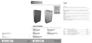
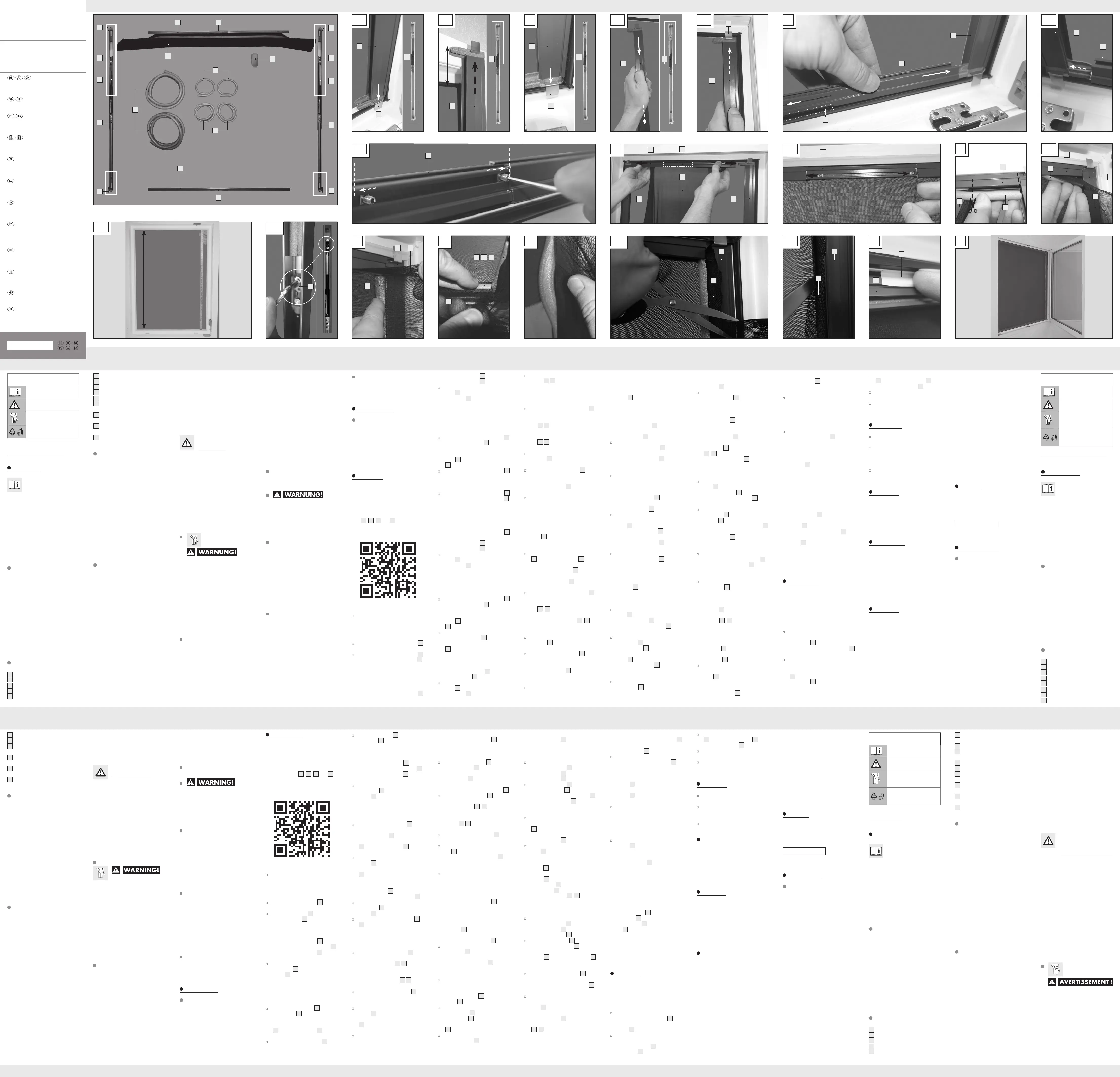
11
7b
9
10
6
8
7 7a
6a
1
3
DOWN
UP
3
4
5
UP
DOWN
3
2
5
4
3
B2
1
3
C
6
1
6a
F
7b1
8
G
7b
10
6
A3
1
5 cm
A A1
4
X
A2
1
3
B
DOWNDOWN
55
1
3
B1
1
5
UP
C2
6
D
7
2
7a
7b
1
E
7
7b
9
E1
7
7b
D1
7
I
7
11
J
C1
2
6
1
9
8
H1
H
5
UP
7b
1
H2
7b
1
383937_2107_V2.0_livh_Insektenschutzfenster_OS.indd 1 08.10.21 13:43
FR/BE FR/BE
Vérifiez que toutes les
pièces sont en parfait état
et correctement montées.
Il existe un risque de bles-
sures si le montage est in-
correct. Les pièces
endommagées peuvent
affecter la sécurité et le
bon fonctionnement.
Manipulez les ciseaux
avec précaution lorsque
vous raccourcissez la
moustiquaire.
Préparation
Outils et matériels
nécessaires
Les outils et matériels indiqués ne sont
pas inclus dans le contenu de la livraison.
‒ paire de ciseaux
‒ mètre ruban / mètre pliant
Montage
Remarque : Avant le montage,
contrôlez la distance extérieure entre le
store et l‘encadrement de fenêtre (dis-
tance minimale 1,5 cm).
Remarque : Ne commencez le mon-
tage que si vous êtes sûr que toutes les
pièces sont présentes et en bon état. Les
pièces
1
,
2
,
6
et
7
sont pourvues
d‘une inscription.
Remarque : Scannez le code QR sui-
vant pour accéder à une animation vidéo
concernant le montage :
les enfants à l‘écart du
produit.
Ce produit peut être uti-
lisé par des enfants âgés
de 8 ans et plus ainsi que
par des personnes ayant
des capacités physiques,
sensorielles ou mentales
réduites ou manquant
d‘expérience ou de connais-
sances,
à la condition
qu‘ils soient surveillés ou
s‘ils ont été informés de
l‘utilisation sûre du produit
et s‘ils comprennent les
risques qui en résultent.
Les enfants ne doivent
pas jouer avec le produit.
Le nettoyage et l‘entretien
ne doivent pas être effec-
tués par des enfants laissés
sans surveillance.
Ce produit doit unique-
ment être installé par une
personne adulte.
DANGER DE MORT !
Lors du montage, démon-
tage ou du nettoyage, ne
vous penchez pas trop
hors de la fenêtre.
Avant le montage et pen-
dant celui-ci, assurez-vous
que la surface sous votre
fenêtre est libre de tout
objet et toute personne.
Vous éviterez ainsi des
dommages possibles ou
blessures pour cause de
chute de pièces.
ATTENTION! RISQUE
DE BLESSURES !
NL/BE NL/BE
3
Klembeugel
4
Kunststof glijstuk
5
Gasveer
6
Dwarsprofiel onder, incl. fixeerplaten
6a
Borstelafdichting onder
7
Dwarsprofiel boven, incl. fixeerplaten
7a
Borstelafdichting boven
7b
Insectengaas
8
Dikke schuimstofrand (elk 150 cm
lang)
9
Dunne schuimstofrand (elk 35 cm
lang)
10
Dunne schuimstofrand (elk 65 cm
lang)
11
Kleefband (130 cm lang)
Technische gegevens
Modelnummer: 06019-IRF–Version
03 / 2022
Breedte: min. 80 cm, uitschuif-
baar tot max. 130 cm
Hoogte: min. 90 cm, uitschuif-
baar tot max. 150 cm
Inbouwdiepte: 1,4 cm
Kan tussen het raam en het rolluik wor-
den geklemd (minimale afstand tussen
rolluik en raamkozijn buiten 1,5 cm).
Het product is alleen geschikt voor ver-
zonken ramen.
Niet geschikt met dubbel openslaande
ramen en ramen met waterdorpel!
Omvang van de levering
Verwijder al het verpakkingsmateriaal en
controleer of alle onderdelen compleet
en onbeschadigd zijn. In geval van een
onvolledige of beschadigde levering kunt
u contact opnemen met de fabrikant.
Gooi met het verpakkingsmateriaal niet
per ongeluk het montagemateriaal weg.
1
zijprofiel rechts, incl. klembeugel, glijstuk,
gasveer (reeds voorgemonteerd)
1 zijprofiel links, incl. klembeugel, glijstuk,
gasveer (reeds voorgemonteerd)
1 dwarsprofiel boven, incl. 2 fixeerplaten
met elk een binnenzeskantschroef
(reeds voorgemonteerd) en insecten-
gaas (reeds voorgemonteerd)
1 dwarsprofiel onder, incl. 2 fixeerplaten
met elk een binnenzeskantschroef
(reeds voorgemonteerd)
2 dikke schuimstofranden (elk 150 cm
lang)
Legenda van de gebruikte
pictogrammen
Lees de gebruiksaanwijzing!
Neem de waarschuwingen
en veiligheidsinstructies in
acht!
Levensgevaar en kans op
ongevallen voor kleuters en
kinderen!
Voer de verpakking en het
product op een milieuvrien-
delijke wijze af!
Telescopische insectenhor
voor het raam
Inleiding
Hartelijk gefeliciteerd met de
aankoop van uw nieuwe pro-
duct. U hebt voor een hoog-
waardig product gekozen. Maak u voor
de eerste ingebruikname vertrouwd met
het product. Lees hiervoor aandachtig de
volgende gebruiksaanwijzing en de vei-
ligheidsvoorschriften. Gebruik het product
alleen zoals beschreven en voor de aan-
gegeven toepassingsgebieden. Bewaar
deze gebruiksaanwijzing op een veilige
plek. Geef, wanneer u het product door-
geeft aan derden, ook alle documenten
mee.
Correct en doelmatig
gebruik
Dit product is bedoeld als bescherming
tegen insecten, zoals bijv. vliegen, aan
ramen in privé-vertrekken. Een ander ge-
bruik dan hiervoor beschreven of een ver-
andering aan het product is niet
toegestaan en kan tot verwondingen
en / of beschadigingen aan het product
leiden. De fabrikant is niet aansprakelijk
voor schade als gevolg van onjuist en on-
doelmatig gebruik. Het product is uitslui-
tend bestemd voor privégebruik en niet
voor commercieel gebruik.
Beschrijving van de
onderdelen
1
Zijprofiel (rechts)
2
Zijprofiel (links)
FR/BE FR/BE FR/BE FR/BE FR/BE FR/BE FR/BE FR/BE FR/BE
La garantie couvre les vices matériels et
de fabrication. Cette garantie ne s’étend
ni aux pièces du produit soumises à une
usure normale (p. ex. des piles) et qui,
par conséquent, peuvent être considérées
comme des pièces d’usure, ni aux dom-
mages sur des composants fragiles,
comme des interrupteurs, des batteries ou
des éléments fabriqués en verre.
Service après-vente
Pour toute question ou réclamation, veuil-
lez nous envoyer un courrier électronique
à l‘adresse e-mail indiquée ci-dessous :
g.kundenservice@gmx.at
IAN 383937_2107
Veuillez indiquer le numéro IAN.
Informations
Distributeur
Goldner GmbH
Ringstraße 24
6830 Rankweil
AUTRICHE
Ou s‘il présente les caractéristiques
définies d‘un commun accord par les
parties ou être propre à tout usage
spécial recherché par l‘acheteur,
porté à la connaissance du vendeur
et que ce dernier a accepté.
Article L217-12 du Code de la
consommation
L‘action résultant du défaut de conformité
se prescrit par deux ans à compter de la
délivrance du bien.
Article 1641 du Code civil
Le vendeur est tenu de la garantie à raison
des défauts cachés de la chose vendue
qui la rendent impropre à l‘usage auquel
on la destine, ou qui diminuent tellement
cet usage que l‘acheteur ne l‘aurait pas
acquise, ou n‘en aurait donné qu‘un
moindre prix, s‘il les avait connus.
Article 1648 1er alinéa du Code
civil
L‘action résultant des vices rédhibitoires
doit être intentée par l‘acquéreur dans un
délai de deux ans à compter de la dé-
couverte du vice.
Les pièces détachées indispensables à
l’utilisation du produit sont disponibles
pendant la durée de la garantie du pro-
duit.
Le produit a été fabriqué selon des cri-
tères de qualité stricts et contrôlé
consciencieusement avant sa livraison. En
cas de défaillance, vous êtes en droit de
retourner ce produit au vendeur. La pré-
sente garantie ne constitue pas une res-
triction de vos droits légaux.
Ce produit bénéficie d‘une garantie de 3
ans à compter de sa date d’achat. La du-
rée de garantie débute à la date d’achat.
Veuillez conserver le ticket de caisse ori-
ginal. Il fera office de preuve d’achat.
Si un problème matériel ou de fabrica-
tion devait survenir dans 3 ans suivant la
date d‘achat de ce produit, nous assu-
rons à notre discrétion la réparation ou le
remplacement du produit sans frais sup-
plémentaires. La garantie prend fin si le
produit est endommagé suite à une utili-
sation inappropriée ou à un entretien dé-
faillant.
Garantie
Article L217-16 du Code de la
consommation
Lorsque l‘acheteur demande au vendeur,
pendant le cours de la garantie commer-
ciale qui lui a été consentie lors de l‘ac-
quisition ou de la réparation d‘un bien
meuble, une remise en état couverte par
la garantie, toute période d‘immobilisa-
tion d‘au moins sept jours vient s‘ajouter
à la durée de la garantie qui restait à
courir. Cette période court à compter de
la demande d‘intervention de l‘acheteur
ou de la mise à disposition pour répara-
tion du bien en cause, si cette mise à dis-
position est postérieure à la demande
d‘intervention.
Indépendamment de la garantie commer-
ciale souscrite, le vendeur reste tenu des
défauts de conformité du bien et des
vices rédhibitoires dans les conditions
prévues aux articles L217-4 à L217-13
du Code de la consommation et aux ar-
ticles 1641 à 1648 et 2232 du Code
Civil.
Article L217-4 du Code de la
consommation
Le vendeur livre un bien conforme au
contrat et répond des défauts de confor-
mité existant lors de la délivrance.
Il répond également des défauts de
conformité résultant de l‘emballage, des
instructions de montage ou de l‘installa-
tion lorsque celle-ci a été mise à sa
charge par le contrat ou a été réalisée
sous sa responsabilité.
Article L217-5 du Code de la
consommation
Le bien est conforme au contrat :
S´il est propre à l‘usage habituelle-
ment attendu d‘un bien semblable et,
le cas échéant :
- s‘il correspond à la description don-
née par le vendeur et posséder les
qualités que celui-ci a présentées à
l‘acheteur sous forme d‘échantillon
ou de modèle ;
- s‘il présente les qualités qu‘un ache-
teur peut légitimement attendre eu
égard aux déclarations publiques
faites par le vendeur, par le produc-
teur ou par son représentant, notam-
ment dans la publicité ou
l‘étiquetage ;
Démontage
Sachez qu‘un nouveau montage est im-
possible voire n‘est pas envisagé. Si vous
souhaitez effectuer un nouveau montage,
il vous faut une moustiquaire neuve.
Passez l‘extrémité courte de la clé à
six pans creux au niveau du profil la-
téral droit
1
en haut au-dessus du
renfort de rebord en mousse (épais)
8
.
Tirez ensuite la clé à six pans creux
vers le bas jusqu‘à ce que le renfort
de rebord en mousse
8
se laisse ex-
traire entièrement avec les doigts
hors du profilé latéral droit
1
.
Procédez de la même manière avec
le profilé latéral gauche
2
, le profil
transversal inférieur
6
et le profilé
transversal supérieur
7
.
Le démontage ultérieur se fait dans
l‘ordre inverse.
Stockez le produit à l’état sec après
le démontage.
Nettoyage
N‘utilisez en aucun cas un produit
nettoyant corrosif ou abrasif.
Nettoyez la moustiquaire et les profi-
lés au moyen d‘un aspirateur réglé
au niveau de plus bas.
Utilisez le cas échéant un produit net-
toyant doux.
Maintenance
Le produit ne nécessite pas de mainte-
nance. Il peut être installé toute l‘année
sur une fenêtre. Le ressort pneumatique
voire la tension de ressort ne nécessitent
également ni entretien, ni contrôle.
Mise au rebut
L’emballage se compose de matières re-
cyclables pouvant être mises au rebut
dans les déchetteries locales.
Le produit est recyclable, soumis
à la responsabilité élargie du
fabricant et collecté séparément.
Votre mairie ou votre municipalité vous
renseigneront sur les possibilités de mise
au rebut des produits usagés.
transversal inférieur
6
, ceci afin
d‘éviter qu‘elle ne se déchire.
Le surplus de renfort de rebord en
mousse
10
peut être raccourci avec
précaution à l‘aide d‘une paire de ci-
seaux.
Remarque : N‘entaillez pas la
moustiquaire
7b
par inadvertance.
Remarque : Le renfort de rebord
en mousse
9
,
10
ne doit pas être
tendu par-dessus le coin.
Retendre :
Procédez comme suit si la moustiquaire
7b
devait être retendue (p. ex. en cas de
plis dans la moustiquaire
7b
) :
À l‘endroit présentant des plis, tirez
vers l‘extérieur le débord sur la mous-
tiquaire
7b
lentement et prudemment
jusqu‘à ce que le renfort de rebord
en mousse se détache. Vous pouvez
alors retendre la moustiquaire
7b
(v. Fig. H).
Remarque: ne tendez pas trop la
moustiquaire
7b
. Il faut seulement
veiller à la lisser.
Réintroduisez ensuite le renfort de re-
bord en mousse dans le profilé cor-
respondant. Le cas échéant, demandez
de l‘aide à une autre personne.
Étape 9
Découpez le débord sur la mousti-
quaire
7b
à droite, à gauche, en
haut et en bas à l‘aide d‘une paire
de ciseaux et avec précaution.
Remarque : N‘entaillez pas la
moustiquaire
7b
par inadvertance.
La paire de ciseaux doit être orientée
vers l‘intérieur de la pièce (v. Fig. H1).
Remarque : Laissez un débord de
3 cm de plus sur la moustiquaire et
pressez ce débord à l‘aide du
manche d‘une cuillère entre le profilé
et le renforcement de rebord en
mousse (v. Fig. H2).
Remarque : En cas de présence d‘une
fente lors du montage du profilé transver-
sal supérieur
7
, utilisez la bande adhé-
sive fournie
11
pour colmater la fente.
Collez pour ceci la bande adhésive
11
dans l‘angle le long de la fente sur le
profilé transversal supérieur
7
en rela-
tion avec le côté intérieur de l‘encadre-
ment de fenêtre (v. Fig. I).
Vous avez effectué avec succès le mon-
tage du produit (v. Fig. J).
Procédez de la même manière sur le
côté gauche du profilé transversal su-
périeur
7
.
Remarque : Le cas échéant, de-
mandez l‘aide d‘une seconde per-
sonne.
Remarque : N‘entaillez pas la
moustiquaire
7b
par inadvertance (v.
Fig. E).
Étape 7 (tendre la moustiquaire
dans les profilés latéraux)
Tendez à présent le renfort de rebord
en mousse (épais)
8
ainsi que la
moustiquaire
7b
en commençant par
le profilé latéral droit
1
supérieur
(v. Fig. F).
Repliez le renfort de rebord en
mousse
8
sur la moustiquaire
7b
et
pressez-les dans le profilé latéral
droit
1
. Maintenez pour ceci la
moustiquaire
7b
légèrement sous
tension. Le cas échéant, demandez
de l‘aide à une autre personne.
Le surplus de renfort de rebord en
mousse
8
peut être raccourci avec
précaution à l‘aide d‘une paire de ci-
seaux.
Remarque : N‘entaillez pas la
moustiquaire
7b
par inadvertance.
Saisissez le second renfort de rebord
en mousse
8
à la main et procédez
de la même manière sur le côté gauche.
Remarque: ne tendez pas trop la
moustiquaire
7b
. Il faut seulement
veiller à la lisser. Lorsque la mousti-
quaire
7b
est trop tirée, les renforts
en mousse
8
du bord peuvent se
détacher des profilés latéraux
1
,
2
,
et la moustiquaire
7b
aussi, par la
même occasion.
Étape 8 (tendre la moustiquaire
en bas)
Tendez à présent le renfort de rebord
en mousse (fin)
10
ainsi que la mous-
tiquaire
7b
en commençant par le
profilé transversal inférieur
6
droit
(v. Fig. G).
Repliez le renfort de rebord en
mousse
10
sur la moustiquaire
7b
et
pressez-les dans le profilé transversal
inférieur
6
. Maintenez pour ceci la
moustiquaire
7b
légèrement sous
tension. Le cas échéant, demandez
de l‘aide à une autre personne.
Veillez à ce que la moustiquaire
7b
ne soit pas trop tendue au niveau
des transitions de profilés du profilé
Remarque : La partie supérieure
centrale de la moustiquaire
7b
est
déjà montée au centre avec un ren-
fort de rebord en mousse dans le
profilé transversal supérieur
7
.
Étendez le profilé transversal supérieur
7
(v. Fig. D) jusqu‘à ce qu‘il soit ali-
gné latéralement avec les deux profi-
lés latéraux
1
2
droit et gauche.
Vous devez pouvoir le glisser sur les
prolongements des deux profilés laté-
raux
1
2
droit et gauche (v. Fig. D).
Veillez à ce que le joint à brosse
7a
soit dirigé vers le haut et vers l‘inté-
rieur de la pièce (v. Fig. D).
Afin que le profilé transversal supé-
rieur
7
puisse être fixé en largeur,
glissez les plaques de fixation au
centre du profilé transversal supérieur
7
resp. jusqu‘à la butée vers la
droite et la gauche (v. Fig. D1).
Fixez ensuite les plaques de fixation.
Vissez pour ceci à la main les deux
vis en tournant dans le sens horaire.
Utilisez pour ceci la clé à six pans
creux fournie.
Remarque : Ne serrez pas les vis
trop fortement pour éviter que le pro-
filé transversal
7
ne se déforme.
Étape 6 (tendre la moustiquaire
en haut)
Remarque : La partie supérieure cen-
trale de la moustiquaire
7b
est déjà mon-
tée au centre avec un renfort de rebord
en mousse dans le profilé transversal su-
périeur
7
.
Découpez un morceau de renfort de
rebord en mousse (fin)
9
à la
bonne dimension. Mesurez pour ceci
la distance du rebord extérieur de
profilé transversal
7
en partant du
côté droit jusqu‘au renfort de rebord
en mousse pré-monté (v. Fig. E).
Afin de fixer la moustiquaire restante
dans le profilé transversal supérieur
sur le côté droit, saisissez à la main
le morceau de renfort de rebord en
mousse
9
découpé à la bonne di-
mension. Repliez-le sur la mousti-
quaire
7b
.
Pressez à présent le morceau de ren-
fort de rebord en mousse
9
dé-
coupé ainsi que la moustiquaire
7b
le long de l‘endroit encore non pré-
monté du profilé transversal supé-
rieur
7
sur le côté droit (v. Fig. E1).
Étape 3
Accrochez le profilé latéral droit
1
au moyen de la pince de maintien
3
en bas sur l‘encadrement de fe-
nêtre (v. Fig. B).
Remarque : Le ressort pneuma-
tique noir
5
à l‘intérieur du profilé
latéral
1
doit se trouver en haut sur
la fenêtre.
Pressez l‘extrémité supérieure du pro-
filé latéral droit
1
vers le bas (v. Fig.
B1) jusqu‘à ce que vous puissiez ac-
crocher la pince de maintien
3
en
haut sur l‘encadrement de fenêtre (v.
Fig. B2). Utilisez votre autre main
pour cette opération. En relâchant
lentement, le profilé latéral droit
1
se fixe de lui-même au travers du res-
sort pneumatique
5
.
Procédez pour le profilé latéral
gauche
2
de la même manière que
pour le profilé latéral droit
1
.
Veillez à ce que les profilés latéraux
1
2
droit et gauche soient bien
alignés sans fente sur l‘encadrement
de fenêtre (tirer de nouveau le cas
échéant).
Étape 4
Étendez le profilé transversal inférieur
6
(v. Fig. C) jusqu‘à ce qu‘il soit ali-
gné latéralement avec les deux profilés
latéraux
1
2
droit et gauche (v.
Fig. C1). Vous devez pouvoir le glis-
ser sur les prolongements des deux
profilés latéraux
1
2
droit et
gauche (v. Fig. C1).
Veillez à ce que le joint à brosse
6a
soit dirigé vers le bas et vers l‘inté-
rieur de la pièce (v. Fig. C).
Afin que le profilé transversal infé-
rieur
6
puisse être fixé en largeur,
glissez les plaques de fixation au
centre du profilé transversal bas
6
resp. jusqu‘à la butée vers la droite
et la gauche.
Fixez ensuite les plaques de fixation.
Vissez pour ceci à la main les deux
vis en tournant dans le sens horaire.
Utilisez pour ceci la clé à six pans
creux fournie (v. Fig. C2).
Remarque : Ne serrez pas les vis
trop fortement pour éviter que le pro-
filé transversal
6
ne se déforme.
Étape 5
Déroulez la moustiquaire
7b
en par-
tant du profilé transversal supérieur
7
.
Étape 1
Mesurez la hauteur de votre enca-
drement de fenêtre (v. Fig. A).
Étape 2a (hauteur d‘encadre-
ment de fenêtre de 90‒95 cm)
Faites glisser le profilé latéral droit
1
jusqu‘à la butée.
Fixez le bloc coulissant en plastique
4
à l‘intérieur du profilé latéral droit
1
. Vissez pour ceci à la main les
deux vis en tournant dans le sens ho-
raire. Utilisez pour ceci la clé hexalo-
bulaire fournie (v. Fig. A1).
Remarque : Ne serrez pas les vis
trop fortement pour éviter que le pro-
filé latéral
1
ne se déforme. Sachez
que le bloc coulissant
4
est fixé
dans le profilé latéral
1
à extraire.
Procédez pour le profilé latéral
gauche
2
de la même manière que
pour le profilé latéral droit
1
.
Remarque : Le bloc coulissant infé-
rieur en métal à vis cruciformes ne
doit pas être détaché.
Étape 2b (hauteur d‘encadre-
ment de fenêtre de 95‒150 cm)
Maintenez le profilé latéral droit
1
à l‘aide de la pince de maintien
3
en bas sur l‘encadrement de fenêtre
(v. Fig. A2).
Remarque : Le ressort pneuma-
tique noir
5
à l‘intérieur du profilé
latéral
1
doit se trouver en haut sur
la fenêtre.
Extrayez le profilé latéral droit
1
su-
périeur de 5 cm de plus que la di-
mension réelle de votre hauteur
d‘encadrement de fenêtre (v. Fig.
A3).
Fixez le bloc coulissant en plastique
4
à l‘intérieur du profilé latéral droit
1
. Vissez pour ceci à la main les
deux vis en tournant dans le sens ho-
raire. Utilisez pour ceci la clé hexalo-
bulaire fournie (v. Fig. A1).
Remarque : Ne serrez pas les vis
trop fortement pour éviter que le pro-
filé latéral
1
ne se déforme. Sachez
que le bloc coulissant
4
est fixé
dans le profilé latéral
1
à extraire.
Procédez pour le profilé latéral
gauche
2
de la même manière que
pour le profilé latéral droit
1
.
Remarque : Le bloc coulissant infé-
rieur en métal à vis cruciformes ne
doit pas être détaché.
CZ CZ CZ PL PL PL PL PL PL PL PL PL PL
PL PL
2 tenká pěnová zesílení okrajů (po 35 cm
délky)
2 tenká pěnová zesílení okrajů (po 65 cm
délky)
1 klíč pro šrouby s vnitřním šestihranem
1 kulatý klíč pro šrouby s vnitřním šestih-
ranem
1 lepící páska
4 šrouby s vnitřním šestihranem (náhradní)
1 návod k montáži
Bezpečnostní
upozornění
PŘED POUŽITÍM SI PŘE-
ČTĚTE NÁVOD KMON-
TÁŽI! NÁVOD K MONTÁŽI
PEČLIVĚ USCHOVEJTE!
PŘI PŘEDÁNÍ VÝROBKU
KNĚMU SOUČASNĚ PŘI-
POJTE I JEHO VEŠKEROU
DOKUMENTACI.
NE-
BEZPEČÍ OHROŽENÍ
ŽIVOTA A NEHODY
PRO MALÉ A VELKÉ
DĚTI! Nikdy nenechá-
vejte děti bez dohledu
svýrobkem a obalovým
materiálem. Hrozí nebez-
pečí udušení. Uchovávejte
výrobek mimo dosah dětí.
Tento výrobek mohou po-
užívat děti od 8 let, osoby
se sníženými fyzickými,
smyslovými nebo dušev-
ními schopnosti nebo s
nedostatečnými zkuše-
nostmi a znalostmi, jest-
liže budou pod dohledem
nebo byly poučeny o
bezpečném používání
7
Horní příčný profil, včetně fixovacích
desek
7a
Horní kartáčové těsnění
7b
Moskytiéra
8
Silné pěnové zesílení okrajů
(po 150 cm délky)
9
Tenké pěnové zesílení okrajů
(po 35 cm délky)
10
Tenké pěnové zesílení okrajů
(po 65 cm délky)
11
Lepící páska (délka 130 cm)
Technická data
Číslo modelu: 06019-IRF–Version
03 / 2022
Šířka: minimální 80 cm, vytaži-
telná maximálně na 130 cm
Výška: minimální 90 cm, vytaži-
telná maximálně na 150 cm
Instalační
hloubka: 1,4 cm
Lze upnout mezi okno a rolety (nejmenší
mezera mezi roletami a okenním rámem
1,5 cm, vnější).
Výrobek je vhodný pouze pro okna s
předsazením.
Výrobek není vhodný pro dvoukřídlá okna
a okna sokenicemi!
Obsah dodávky
Odstraňte všechny obalové materiály a
zkontrolujte úplnost všech dílů a jejich ne-
porušenost. V případě neúplného nebo
poškozeného obsahu dodávky se obraťte
na výrobce. Neodstraňte nedopatřením
do odpadu montážní materiál spolu s
obalovým materiálem.
1 pravý postranní profil, včetně přídržné
svorky, kluzáku, plynové vzpěry (před-
montované)
1 levý postranní profil, včetně přídržné
svorky, kluzáku, plynové vzpěry (před-
montované)
1 horní příčný profil, včetně 2 fixovacích
desek se šroubem s vnitřním šestihra-
nem (předmontovaný) a moskytiéra
(předmontovaná)
1 dolní příčný profil, včetně 2 fixovacích
desek se šroubem s vnitřním šestihra-
nem (předmontovaný)
2 silná pěnová zesílení okrajů (po 150 cm
délky)
Legenda použitých piktogramů
Přečtěte si návod kpoužití!
Respektujte výstražné a bez-
pečnostní pokyny!
Nebezpečí ohrožení života
a nehody malých a velkých
dětí!
Obal a výrobek likvidujte
ekologicky!
Ochrana proti hmyzu na
okno
Úvod
Blahopřejeme Vám ke koupi
nového výrobku. Rozhodli jste
se pro kvalitní výrobek. Před
prvním uvedením do provozu se seznamte
s výrobkem. K tomu si pozorně přečtěte
následující návod k obsluze a bezpeč-
nostní pokyny. Používejte výrobek jen po-
psaným způsobem a pouze pro uvedené
oblasti použití. Uschovejte si tento návod
na bezpečném místě. Všechny podklady
vydejte při předání výrobku i třetí osobě.
Použití ke stanovenému
účelu
Tento výrobek je určen kochraně proti
hmyzu na oknech, např. jako jsou mou-
chy, v privátních obytných prostorech. Ja-
kékoliv jiné použití, než je výše uvedeno,
nebo provedení změny na výrobku ne-
jsou přípustné a mohou vést kúrazům a
kpoškození výrobku. Výrobce neručí za
škody vzniklé jiným použitím než kpo-
psanému účelu. Tento výrobek je určen
pouze pro privátní použití, není vhodný
pro živnostenské podnikání.
Popis dílů
1
Pravý postranní profil
2
Levý postranní profil
3
Přídržná svorka
4
Umělohmotný kluzák
5
Plynová vzpěra
6
Dolní příčný profil, včetně fixovacích
desek
6a
Dolní kartáčové těsnění
Świadczenie gwarancyjne obejmuje wady
materiałowe i fabryczne. Gwarancja nie
obejmuje części produktu ulegających
normalnemu zużyciu, uznawanych za
części zużywalne (np. baterie) oraz
uszkodzeń części łamliwych, np. prze-
łączników, akumulatorów lub wykona-
nych ze szkła.
Zgodnie z Kodeksem Cywilnym art. 581
§1 wraz z wymianą urządzenia lub waż-
nej części czas gwarancji rozpoczyna się
na nowo.
Serwis
W razie pytań lub reklamacji proszę
napisać do nas wiadomość na podany
poniżej adres e-mail:
g.kundenservice@gmx.at
IAN 383937_2107
Proszę podać numer IAN.
Informacje
Podmiot wprowadzający
do obrotu
Goldner GmbH
Ringstraße 24
6830 Rankweil
AUSTRIA
Po demontażu przechowywać produkt
w suchym miejscu.
Czyszczenie
W żadnym wypadku nie używać
żrących ani szorujących środków
czyszczących.
Oczyścić tkaninę do ochrony przed
owadami i profile odkurzacze ręcz-
nym ustawionym na słabe ssanie
(najniższy poziom).
W razie potrzeby należy użyć ła-
godnego środka czyszczącego.
Konserwacja
Niniejszy produkt nie wymaga konserwa-
cji. Może pozostać zamontowany na oknie
przez cały rok. Sprężyna gazowa lub na-
pięcie sprężyny również nie wymagają
konserwacji ani kontroli.
Utylizacja
Opakowanie wykonane jest z materia-
łów przyjaznych dla środowiska, które
można przekazać do utylizacji w lokal-
nym punkcie przetwarzania surowców
wtórnych.
Informacji na temat możliwości utylizacji
wyeksploatowanego produktu udziela
urząd gminy lub miasta.
Gwarancja
Produkt wyprodukowano według wysokich
standardów jakości i poddano skrupulat-
nej kontroli przed wysyłką. W przypadku
wad produktu nabywcy przysługują usta-
wowe prawa. Gwarancja nie ogranicza
ustawowych praw nabywcy produktu.
Produkt objęte jest 3 gwarancją, licząc
od daty zakupu. Gwarancja wygasa w
razie zawinionego przez użytkownika
uszkodzenia produktu, niewłaściwego
użycia lub konserwacji.
W przypadku wystąpienia w ciągu 3 lat
od daty zakupu wad materiałowych lub
fabrycznych, dokonujemy – według wła-
snej oceny – bezpłatnej naprawy lub wy-
miany produktu.
Następnie ponownie wcisnąć pian-
kowe wzmocnienie krawędzi w dany
profil. W tym celu należy ew. popro-
sić o pomoc drugą osobę.
Krok 9
Odciąć nadmiar tkaniny do ochrony
przed owadami
7b
po prawej, lewej
stronie i u dołu ostrożnie nożyczkami.
Wskazówka: Nie ciąć przy tym
omyłkowo w tkaninie do ochrony
przed owadami
7b
. Nożyczki wska-
zują przy tym zawsze do wewnątrz
(patrz rys. H1).
Wskazówka: Pozostawić przy tym
3 cm więcej tkaniny do ochrony przed
owadami jako nadmiar, a następnie
wcisnąć ten nadmiar trzonkiem łyżki
między profil a piankowe wzmocnie-
nie krawędzi (patrz rys. H2).
Wskazówka: Jeśli przy montażu gór-
nego profilu poprzecznego
7
istnieje
szczelina, użyć dołączonej taśmy kleją-
cej
11
, aby zamknąć szczelinę. Przy tym
przykleić taśmę klejącą
11
w kącie wzdłuż
szczeliny na górnym profilu poprzecz-
nym
7
w połączeniu z wewnętrzną
stroną ramy okiennej (patrz rys. I).
W ten sposób produkt jest właściwie za-
montowany (patrz rys. J).
Demontaż
Proszę pamiętać, że ponowny montaż
nie jest możliwy lub przewidziany. Jeśli
chce się podjąć ponownego montażu,
proszę pamiętać, że w tym celu potrzebna
jest nowa tkanina do ochrony przed owa-
dami.
Wprowadzić krótki koniec klucza
trzpieniowego szciokątnego przy
prawym profilu bocznym
1
u góry
nad piankowym wzmocnieniem kra-
wędzi (grubym)
8
.
Następnie pociągnąć klucz trzpieniowy
sześciokątny na tyle do dołu, aż bę-
dzie można całkowicie wyjąć piankowe
wzmocnienie krawędzi
8
palcami z
prawego profilu bocznego
1
.
Dokładnie tak samo postąpić przy le-
wym profilu bocznym
2
, przy dol-
nym profilu poprzecznym
6
i przy
górnym profilu poprzecznym
7
.
Dalszy demontaż wykonuje się od-
powiednio w odwrotnej kolejności.
Wskazówka: Nie napinać tkaniny
do ochrony przed owadami
7b
zbyt
mocno. Powinno się tylko wygładzić
możliwe marszczenia. Jeśli tkaninę do
ochrony przed owadami
7b
napnie
się zbyt mocno, wzmocnienia krawę-
dzi
8
z pianki mogą się oddzielić z
profili bocznych
1
,
2
i przez to też z
tkaniny do ochrony przed owadami
7b
.
Krok 8 (zamocować u dołu tka-
ninę do ochrony przed owadami)
Rozpocząć teraz przy dolnym profilu
poprzecznym
6
prawym od napięcia
piankowego wzmocnienia krawędzi
(cienkiego)
10
z tkaniną do ochrony
przed owadami
7b
(patrz rys. G).
Owinąć piankowe wzmocnienie kra-
wędzi
10
tkaniną do ochrony przed
owadami
7b
i wcisnąć je razem w
dolny profil poprzeczny
6
. W tym
celu nieco naciągnąć tkaninę do
ochrony przed owadami
7b
. W tym
celu należy ew. poprosić o pomoc
drugą osobę.
Pamiętać o tym, aby w przypadku
łączeń profili dolnego profilu po-
przecznego
6
nie napinać tkaniny
do ochrony przed owadami
7b
zbyt
mocno, ponieważ w innym razie może
się rozerwać.
Nadmiar piankowego wzmocnienia
do ochrony przed owadami
10
możn
a
ostrożnie skrócić nożyczkami.
Wskazówka: Nie ciąć przy tym
omyłkowo w tkaninie do ochrony
przed owadami
7b
.
Wskazówka: Piankowe wzmoc-
nienie krawędzi
9
,
10
nie może
być mocowane na narożnikach.
Ponowne napinanie:
Należy postępować następująco, jeśli
tkanina do ochrony przed owadami
7b
ma być ponownie napięta (np. w przy-
padku marszczeń tkaniny do ochrony
przed owadami
7b
):
Powoli i ostrożnie wyciągać w miej-
scu z marszczeniami nadmiar tkaniny
do ochrony owadami
7b
, aż pian-
kowe wzmocnienie krawędzi od-
dzieli się. Teraz można ponownie
napiąć tkaninę do ochrony przed
owadami
7b
(patrz rys. H).
Wskazówka: Nie napinać tkaniny
do ochrony przed owadami
7b
zbyt
mocno. Powinno się tylko wygładzić
możliwe marszczenia.
z piankowym wzmocnieniem krawędzi w
górnym profilu poprzecznym
7
.
Przyciąć odpowiednio kawałek
piankowe wzmocnienie krawędzi
(cienkie)
9
. W tym celu należy
zmierzyć odległość od zewnętrznej
krawędzi profilu poprzecznego
7
od prawej strony do fabrycznie za-
montowanego piankowego wzmoc-
nienia krawędzi (patrz rys. E).
Aby zamontować pozostałą tkaninę
do ochrony przed owadami w gór-
nym profilu poprzecznym po prawej
stronie, wziąć do ręki odpowiednio
przycięty kawałek piankowego wzmoc-
nien
ia krawędzi
9
. Owinąć je tka-
niną do ochrony przed owadami
7b
.
Następnie wcisnąć odpowiednio
przycięty kawałek piankowego wzmoc-
nienia
krawędzi
9
wraz z tkaniną do
ochrony przed owadami
7b
wzdłuż
nie zamontowanego jeszcze górnego
profilu poprzecznego
7
po prawej
stronie (patrz rys. E1).
Tak samo należy postąpić po lewej
stronie górnego profilu poprzecz-
nego
7
.
Wskazówka: W tym celu należy
ew. poprosić o pomoc drugą osobę.
Wskazówka: Nie ciąć przy tym
omyłkowo w tkaninie do ochrony
przed owadami
7b
(patrz rys. E).
Krok 7 (napiąć tkaninę do ochrony
przed owadami w profilach
bocznych)
Rozpocząć teraz przy prawym pro-
filu bocznym
1
górnym od napięcia
piankowego wzmocnienia krawędzi
(grubego)
8
z tkaniną do ochrony
przed owadami
7b
(patrz rys. F).
Owinąć piankowe wzmocnienie kra-
wędzi
8
tkaniną do ochrony przed
owadami
7b
i wcisnąć je razem w
prawy profil boczny
1
. W tym celu
nieco naciągnąć tkaninę do ochrony
przed owadami
7b
. W tym celu na-
leży ew. poprosić o pomoc drugą
osobę.
Nadmiar piankowego wzmocnienia
do ochrony przed owadami
8
można ostrożnie skrócić nożyczkami.
Wskazówka: Nie ciąć przy tym
omyłkowo w tkaninie do ochrony
przed owadami
7b
.
Wziąć do ręki drugie piankowe wzmoc-
nienie
krawędzi
8
i postępować tak
samo po lewej stronie.
Aby dolny profil poprzeczny
6
mógł
być zamocowany na szerokość, prze-
sunąć płyty mocujące w środku dol-
nego profilu poprzecznego
6
każdorazowo do oporu w prawo i w
lewo.
Następnie zamocować płyty mocu-
jące. W tym celu ręcznie przykręcić
dwie śruby w kierunku wskazówek
zegara. Użyć do tego dołączonego
klucza trzpieniowego szciokąt-
nego (patrz rys. C2).
Wskazówka: Nie przekręcać przy
tym śrub, ponieważ w innym razie
profil poprzeczny
6
może się zde-
formować.
Krok 5
Rozwinąć tkaninę do ochrony przed
owadami
7b
z górnego profilu po-
przecznego
7
.
Wskazówka: Górna środkowa
część tkaniny do ochrony przed owa-
dami
7b
jest już zamontowana fa-
brycznie na środku z piankowym
wzmocnieniem krawędzi w górnym
profilu poprzecznym
7
.
Rozciągnąć górny profil boczny
7
na tyle (patrz rys. D), aż z boku będzie
szczelnie przylegał do obu profili
bocznych
1
2
prawego i lewego.
Musi być możliwe wsunięcie go na
przedłużeniach przy obu profilach
1
,
2
prawym i lewym (patrz rys. D).
Zwrócić uwagę na to, aby uszczelka
szczotkowa
7a
była skierowana w
górę do wnętrza (patrz rys. D).
Aby górny profil poprzeczny
7
mógł być zamocowany na szero-
kość, przesunąć płyty mocujące w
środku górnego profilu poprzecz-
nego
7
każdorazowo do oporu
w prawo i w lewo (patrz rys. D1).
Następnie zamocować płyty mocu-
jące. W tym celu ręcznie przykręcić
dwie śruby w kierunku wskazówek
zegara. Użyć do tego dołączonego
klucza trzpieniowego szciokątnego.
Wskazówka: Nie przekręcać
przy tym śrub, ponieważ w innym ra-
zie profil poprzeczny
7
może się
zdeformować.
Krok 6 (napiąć u góry tkaninę do
ochrony przed owadami)
Wskazówka: Górna środkowa część
tkaniny do ochrony przed owadami
7b
jest już zamontowana fabrycznie na środku
prawego profilu bocznego
1
. W
tym celu ręcznie przykręcić dwie
śruby w kierunku wskazówek zegara.
W tym celu użyć dołączonego klu-
cza trzpieniowego szciokątnego
okrągłego (patrz rys. A1).
Wskazówka: Nie przekręcać
śrub, ponieważ w innym razie profil
boczny
1
może się zdeformować.
Pamiętać o tym, że element ślizgowy
4
mocowany jest w wysuwanym
profilu bocznym
1
.
W przypadku lewego profilu bocz-
nego
2
postępować dokładnie tak
samo jak przy prawym profilu bocz-
nym
1
.
Wskazówka: Dolny metalowy ele-
ment ślizgowy ze śrubami z rowkiem
krzyżowym nie może być odkręcany.
Krok 3
Zawiesić prawy profil boczny
1
za
pomocą klamry mocującej
3
u dołu
przy ramie okna (patrz rys. B).
Wskazówka: Czarna sprężyna
gazowa
5
musi znajdować się we-
wnątrz profilu bocznego
1
u góry
na oknie.
Wcisnąć górny koniec prawego pro-
filu bocznego
1
w dół (patrz rys.
B1), aż będzie można zawiesić
klamrę mocującą
3
u góry przy ra-
mie okiennej (patrz rys. B2). W tym
celu użyć do pomocy drugiej ręki.
Poprzez powolne odciążanie prawy
profil boczny
1
mocuje się sam za
pomocą sprężyny gazowej
5
.
W przypadku lewego profilu bocz-
nego
2
postępować dokładnie tak
samo jak przy prawym profilu bocz-
nym
1
.
Zwrócić uwagę na to, aby profile
boczne
1
2
prawy i lewy przyle-
gały ściśle bez szczeliny do ramy
okiennej (ewentualnie nieco dosunąć).
Krok 4
Rozciągnąć dolny profil boczny
6
na tyle (patrz rys. C), aż z boku bę-
dzie szczelnie przylegał do obu pro-
fili bocznych
1
2
prawego i lewego
(patrz rys. C1). Musi być możliwe
wsunięcie go na przedłużeniach przy
obu profilach
1
2
prawym i lewym
(patrz rys. C1).
Zwrócić uwagę na to, aby uszczelka
szczotkowa
6a
była skierowana w
dół do wnętrza (patrz rys. C).
Krok 1
Zmierzyć wysokość ramy okiennej
swojego okna (patrz rys. A).
Krok 2a (wysokość ramy okiennej
90‒95 cm)
Zsunąć prawy profil boczny
1
do oporu.
Zamocować element ślizgowy z two-
rzywa sztucznego
4
wewnątrz pra-
wego profilu bocznego
1
. W tym
celu ręcznie przykręcić dwie śruby w
kierunku wskazówek zegara. W tym
celu użyć dołączonego klucza trzpie-
niowego sześciokątnego okrągłego
(patrz rys. A1).
Wskazówka: Nie przekręcać
śrub, ponieważ w innym razie profil
boczny
1
może się zdeformować.
Pamiętać o tym, że element ślizgowy
4
mocowany jest w wysuwanym
profilu bocznym
1
.
W przypadku lewego profilu bocz-
nego
2
postępować dokładnie tak
samo jak przy prawym profilu bocz-
nym
1
.
Wskazówka: Dolny metalowy ele-
ment ślizgowy ze śrubami z rowkiem
krzyżowym nie może być odkręcany.
Krok 2b (wysokość ramy okiennej
95‒150 cm)
Przytrzymać prawy profil boczny
1
klamrą mocującą
3
u dołu przy ra-
mie okna (patrz rys. A2).
Wskazówka: Czarna sprężyna
gazowa
5
musi znajdować się we-
wnątrz profilu bocznego
1
u góry
na oknie.
Wyciągnąć prawy profil boczny
1
u góry o 5 cm dalej niż wynosi fak-
tyczna wysokość ramy okiennej
(patrz rys. A3).
Zamocować element ślizgowy z two-
rzywa sztucznego
4
wewnątrz
ciała spowodowanych
spadającymi częściami.
OSTROŻNIE! NIEBEZ-
PIECZEŃSTWO OB-
RAŻEŃ CIAŁA! Należy
upewnić się, że wszystkie
części zostały zamonto-
wane w należyty sposób
oraz że nie są uszkodzone.
W przypadku wadliwego
montażu istnieje niebez-
pieczeństwo obrażeń
ciała. Uszkodzone ele-
menty mogą mieć wpływ
na bezpie
czeństwo i funk-
cjonowanie.
Proszę postępować
ostrożnie z nożyczkami
podczas skracania tka-
niny do ochrony przed
owadami.
Przygotowanie
Potrzebne narzędzia i
materiały
Wymienione narzędzia i materiały nie są
częścią zestawu.
‒ nożyczki
‒ miara krawiecka / calówka
Montaż
Wskazówka: Przed montażem należy
sprawdzić zewnętrzną odległość między
roletą a ramą okienną (minimalna odle-
głość 1,5 cm).
Wskazówka: Proszę rozpocząć mon-
taż dopiero po upewnieniu się, że są
wszystkie części i nie są uszkodzone.
Części
1
,
2
,
6
i
7
są opisane.
Wskazówka: Proszę zeskanować
następujący kod QR do animowanego
filmiku montażowego:
z materiałem opakowa-
niowym oraz produktem
bez nadzoru. Niebezpie-
czeństwo uduszenia.
Produkt należy przecho-
wywać poza zasięgiem
dzieci.
Niniejszy produkt może
być używany przez dzieci
od lat 8 oraz przez osoby
z obniżonymi zdolnościami
fizycznymi, sensorycznymi
lub mentalnymi lub bra-
kiem doświadczenia i/
lub wiedzy, jeśli pozo-
stają pod nadzorem lub
zostały pouczone w kwe-
stii bezpiecznego użycia
produktu i rozumieją wy-
nikające z niego zagro-
żenia. Dzieci nie mogą
bawić się produktem.
Czyszczenie i konserwa-
cja nie mogą być wyko-
nywane przez dzieci bez
nadzoru.
Niniejszy produkt może
być montowany jedynie
przez osobę dorosłą.
ZAGROŻENIE ŻYCIA!
Podczas montażu, demon-
tażu oraz czyszczenia
nie należy za bardzo wy-
chylać się o przez okno.
Przed montażem upewnić
się, że na powierzchni pod
oknem w czasie montażu
nie znajdują się przed-
mioty lub osoby. Dzięki
temu uniknie się możli-
wych szkód lub obrażeń
1 profil boczny lewy, z klamrą mocującą,
elementem ślizgowym, sprężyną ga-
zową (już zamontowane fabrycznie)
1 profil poprzeczny górny, z 2 płytami
mocującymi każdorazowo z jedną
śrubą z łbem walcowym z gniazdem
sześciokątnym (już zamontowane fa-
brycznie) oraz tkanina do ochrony
przed owadami (już zamontowana fa-
brycznie)
1 profil poprzeczny dolny, z 2 płytami
mocującymi, każdorazowo z jedną
śrubą z łbem walcowym z gniazdem
sześciokątnym (już zamontowana fa-
brycznie)
2 grube piankowe wzmocnienie krawę-
dzi (po 150 cm długości)
2 cienkie piankowe wzmocnienie krawę-
dzi (po 35 cm długości)
2 cienkie piankowe wzmocnienie krawę-
dzi (po 65 cm długości)
1 klucz trzpieniowy sześciokątny
1 klucz trzpieniowy sześciokątny okrągły
1 taśma klejąca
4 śruby z łbem walcowym z gniazdem
sześciokątnym (zamienne)
1 instrukcja montażu
Wskazówki
bezpieczeństwa
PRZED UŻYCIEM PRZE-
CZYTAĆ INSTRUKC
MONTAŻU! STARANNIE
PRZECHOWAĆ INSTRUK-
CJĘ MONTAŻU! W PRZY-
PADKU PRZEKAZANIA
PRODUKTU INNE OSOBIE
NALEŻY DOŁĄCZYĆ DO
NIEGO CAŁĄ JEGO DO-
KUMENTACJĘ.
NIEBEZPIECZEŃSTWO
UTRATY ŻYCIA LUB
WYPADKU DLA
DZIECI! Nigdy nie na-
leży pozostawiać dzieci
Opis części
1
Profil boczny (strona prawa)
2
Profil boczny (strona lewa)
3
Klamra mocująca
4
Element ślizgowy z tworzywa sztucz-
nego
5
Sprężyna gazowa
6
Profil poprzeczny dolny, włącznie z
płytami mocującymi
6a
Uszczelka szczotkowa dolna
7
Profil poprzeczny górny, włącznie z
płytami mocującymi
7a
Uszczelka szczotkowa górna
7b
Tkanina do ochrony przed owadami
8
Grube piankowe wzmocnienie
krawędzi (po 150 cm długości)
9
Cienkie piankowe wzmocnienie
krawędzi (po 35 cm długości)
10
Cienkie piankowe wzmocnienie
krawędzi (po 65 cm długości)
11
Taśma klejąca (130 cm długości)
Dane techniczne
Numer modelu: 06019-IRF–Version
03 / 2022
Szerokość: min. 80 cm, rozsuwane
do maks. 130 cm
Wysokość: min. 90 cm, rozsuwane
do maks. 150 cm
Głębokość
montażu: 1,4 cm
Możliwość zamontowania między oknem
a roletami (minimalna odległość między
roletami a ramami okiennym na zewnątrz
1,5 cm).
Produkt nadaje się tylko do okien niezli-
cowanych.
Nie nadaje się do okien dwuskrzydłowych
ani do okien z okapnikiem!
Zawartość
Usunąć wszystkie materiały opakowania
i sprawdzić, czy wszystkie części są kom-
pletne i nieuszkodzone. W razie niekom-
pletnej lub uszkodzonej dostawy proszę
zwrócić się do producenta. Uważać, by
omyłkowo nie usunąć materiału montażo-
wego wraz z materiałem opakowaniowym.
1 profil boczny prawy, z klamrą mocu-
jącą, elementem ślizgowym, sprężyną
gazową (już zamontowane fabrycznie)
PL NL/BE NL/BE NL/BE NL/BE NL/BE NL/BE NL/BE NL/BE NL/BE NL/BE
Legenda zastosowanych
piktogramów
Przeczytać instrukcję obsługi!
Przestrzegać wskazówek
ostrzegawczych i bezpie-
czeństwa!
Niebezpieczeństwo utraty
życia i wypadku dla dzieci!
Opakowanie oraz produkt
zutylizować zgodnie z zale-
ceniami dotyczącymi ochrony
środowiska naturalnego!
Teleskopowa osłona przed
owadami na okno
Wstęp
Gratulujemy Państwu zakupu
nowego produktu. Zdecydo-
wali się Państwo na zakup
produktu najwyższej jakości. Przed uru-
chomieniem urządzenia po raz pierwszy
zapoznaj się z nim. W tym celu przeczy-
taj uważnie poniższą instrukcję obsługi
oraz wskazówki dotyczące bezpieczeń-
stwa. Produkt należy użytkować w spo-
sób tu opisany i zgodnie z określonym
zakresem zastosowania. Należy prze-
chowywać tę instrukcję w bezpiecznym
miejscu. Przekazując produkt innej oso-
bie, należy również przekazać wszystkie
dokumenty.
Zastosowanie zgodne z
przeznaczeniem
Ten produkt przewidziany jest do stoso-
wania jako ochrona przed owadami, np.
muchami, w prywatnych pomieszczeniach
mieszkalnych na oknach. Użycie inne niż
wyżej opisane lub dokonywanie zmian
produktu nie jest dozwolone i może pro-
wadzić do jego uszkodzenia. Producent
nie ponosi odpowiedzialności za szkody
powstałe wskutek użycia produktu nie-
zgodnie z jego przeznaczeniem. Produkt
przeznaczony jest wyłącznie do użytku
prywatnego, nie zaś do zastosowania
komercyjnego.
– gratis voor u gerepareerd of vervan-
gen. Deze garantie komt te vervallen als
het product beschadigd wordt, niet cor-
rect gebruikt of onderhouden wordt.
De garantie geldt voor materiaal- en pro-
ductiefouten. Deze garantie is niet van
toepassing op productonderdelen, die
onderhevig zijn aan normale slijtage en
hierdoor als aan slijtage onderhevige on-
derdelen gelden (bijv. batterijen) of voor
beschadigingen aan breekbare onderde-
len, zoals bijv. schakelaars, accu’s of der-
gelijke onderdelen, die gemaakt zijn van
glas.
Service
Bij vragen of reclamaties kunt u een
e-mail sturen naar het hieronder vermelde
e-mailadres:
g.kundenservice@gmx.at
IAN 383937_2107
Vermeld alstublieft uw IAN-nummer.
Informatie
Distributeur
Goldner GmbH
Ringstraße 24
6830 Rankweil
OOSTENRIJK
De verdere demontage geschiedt in
principe in omgekeerde volgorde.
Bewaar het product na de demontage
op een droge plek.
Reiniging
Gebruik in geen geval bijtende of
schurende reinigingsmiddelen.
Reinig het insectengaas en de profie-
len met een handstofzuiger op de
laagste stand (weinig zuigkracht).
Gebruik zo nodig een mild schoon-
maakmiddel.
Onderhoud
Het product is onderhoudsvrij. Het kan het
hele jaar door aan het raam gemonteerd
blijven. De gasveren resp. de veerspanning
hebben eveneens geen onderhoud en
geen controle nodig.
Afvoer
De verpakking bestaat uit milieuvriende-
lijke grondstoffen die u via de plaatselijke
recyclingcontainers kunt afvoeren.
Informatie over de mogelijkheden om het
uitgediende product na gebruik te verwij-
deren, verstrekt uw gemeentelijke overheid.
Garantie
Het product wordt volgens strenge kwali-
teitsrichtlijnen zorgvuldig geproduceerd
en voor levering grondig getest. In geval
van schade aan het product kunt u recht-
matig beroep doen op de verkoper van
het product. Deze wettelijke rechten wor-
den door onze hierna vermelde garantie
niet beperkt.
Op dit product verlenen wij 3 jaar garan-
tie vanaf aankoopdatum. De garantiepe-
riode start op de dag van aankoop.
Bewaar de originele kassabon alstublieft.
Dit document is nodig als bewijs voor
aankoop.
Wanneer binnen 3 jaar na de aankoop-
datum van dit product een materiaal- of
productiefout optreedt, dan wordt het
product door ons – naar onze keuze
de schuimstofrand los komt. Vervol-
gens kunt u het insectengaas
7b
naspannen (zie afb. H).
Opmerking: span het insecten-
gaas
7b
niet te strak. Alleen eventuele
plooien moeten worden gladgestreken.
Druk daarna de schuimstofrand weer
in het betreffende profiel. Vraag even-
tueel een tweede persoon om hulp.
Stap 9
Knip het uitstekende insectengaas
7b
rechts, links, boven en beneden voor-
zichtig met een schaar af.
Opmerking: knip daarbij niet per
ongeluk in het insectengaas
7b
. De
schaar is hierbij altijd naar het interi-
eur gericht (zie afb. H1).
Opmerking: laat hierbij 3 cm meer
van het insectengaas uitsteken en
druk dit uitstekende gedeelte vervol-
gens met de steel van een lepel tus-
sen het profiel en randversterking van
schuimstof (zie afb. H2).
Opmerking: als er bij de montage van
het bovenste dwarsprofiel
7
een kier
overblijft, gebruik dan het meegeleverde
kleefband
11
om de kier te dichten. Plak
daarbij het kleefband
11
in een hoek langs
de kier op het bovenste dwarsprofiel
7
en de binnenkant van het raamkozijn (zie
afb. I).
U hebt het product nu succesvol gemon-
teerd (zie afb. J).
Demontage
Houd er rekening mee dat het niet moge-
lijk resp. de bedoeling is om het product
nogmaals te monteren. Als u het product
opnieuw wilt monteren, bedenk dan dat
u hiervoor nieuw insectengaas nodig hebt.
Steek het korte uiteinde van de binn-
enzeskantsleutel in het rechter zijpro-
fiel
1
bovenaan ter hoogte van de
schuimstofrand (dik)
8
.
Trek de binnenzeskantsleutel vervol-
gens zover naar beneden tot u de
schuimstofrand
8
met de vingers
volledig uit het rechter zijprofiel
1
kunt trekken.
Ga op dezelfde manier te werk bij
het linker zijprofiel
2
, bij het onder-
ste dwarsprofiel
6
en bij het boven-
ste dwarsprofiel
7
.
Sla het insectengaas
7b
om de
schuimstofrand
8
heen en druk het
samen in het rechter zijprofiel
1
.
Houd daarbij het insectengaas
7b
een beetje op spanning. Vraag hier-
bij eventueel een tweede persoon
om hulp.
Het overblijvende stuk schuim-
stofrand
8
kunt u voorzichtig met
een schaar afknippen.
Opmerking: knip daarbij niet per
ongeluk in het insectengaas
7b
.
Neem de tweede schuimstofrand
8
erbij en doe hetzelfde aan de linker
zijde.
Opmerking: span het insecten-
gaas
7b
niet te strak. Alleen eventuele
plooien moeten worden gladgestreken.
Als u het insectengaas
7b
te strak spant,
kunnen de met schuimstof
8
versterkte
randen uit de zijprofielen
1
,
2
los-
raken en zodoende ook het insecten-
gaas
7b
.
Stap 8 (insectengaas onder
inspannen)
Begin vervolgens bij het onderste
dwarsprofiel
6
rechts de schuim-
stofrand (dun)
10
samen met het
insectengaas
7b
in te spannen
(zie afb. G).
Sla het insectengaas
7b
om de schuim-
stofrand
10
heen en druk het samen
in het onderste dwarsprofiel
6
. Houd
daarbij het insectengaas
7b
een bé-
tje op spanning. Vraag hierbij eventu-
eel een tweede persoon om hulp.
Zorg ervoor dat bij de profielover-
gangen van het onderste dwarspro-
fiel
6
het insectengaas
7b
niet te
strak wordt gespannen omdat het
dan kan inscheuren.
Het overblijvende stuk schuim-
stofrand
10
kunt u voorzichtig met
een schaar afknippen.
Opmerking: knip daarbij niet per
ongeluk in het insectengaas
7b
.
Opmerking: de schuimstofrand
9
,
10
mag niet over de hoek worden
gespannen.
Naspannen:
Ga als volgt te werk als het insectengaas
7b
nogmaals nagespannen moet worden
(bijv. bij kreukels/vouwen in het insecten-
gaas
7b
):
Trek op de plek met de kreukels het
uitstekende insectengaas
7b
lang-
zaam en voorzichtig naar buiten tot
Zorg ervoor dat de borstelafdichting
7a
naar boven naar het interieur wijst
(zie afb. D).
Om het bovenste dwarsprofiel
7
in de breedte vast te kunnen zetten,
schuift u de fixeerplaten in het mid-
den van het bovenste dwarsprofiel
7
elk tot aan de aanslag naar rechts
en links (zie afb. D1).
Zet vervolgens de fixeerplaten vast.
Draai daarvoor de twee schroeven
met de klok mee handmatig vast.
Gebruik hiervoor de meegeleverde
binnenzeskantsleutel.
Opmerking: draai de schroeven
niet te vast omdat het dwarsprofiel
7
dan kan vervormen.
Stap 6 (insectengaas boven
inspannen)
Opmerking: het bovenste middelste
deel van het insectengaas
7b
is al voor-
zien van een schuimstofrand en in het
midden van het bovenste dwarsprofiel
7
voorgemonteerd.
Knip een stukje schuimstofrand (dun)
9
op maat. Meet hiervoor de af-
stand vanaf de buitenkant van het
dwarsprofiel
7
aan de rechter zijde
tot aan de voorgemonteerde schuim-
stofrand (zie afb. E).
Om het resterende insectengaas in
het bovenste dwarsprofiel aan de
rechter zijde vast te zetten, neemt u
het op maat geknipte stuk schuim-
stofrand
9
er bij. Sla het insecten-
gaas
7b
hier omheen.
Druk vervolgens het op maat geknipte
stuk schuimstofrand
9
samen met
het insectengaas
7b
in het nog niet
voorgemonteerde gedeelte van het
bovenste dwarsprofiel
7
aan de
rechterkant (zie afb. E1).
Doe hetzelfde aan de linkerkant van
het bovenste dwarsprofiel
7
.
Opmerking: vraag hierbij eventu-
eel een tweede persoon om hulp.
Opmerking: knip daarbij niet per
ongeluk in het insectengaas
7b
(zie
afb. E).
Stap 7 (insectengaas in de zijpro-
fielen spannen)
Begin vervolgens bij het rechter zij-
profiel
1
bovenaan de schuim-
stofrand (dik)
8
samen met het
insectengaas
7b
in te spannen
(zie afb. F).
aan de bovenkant van het raamko-
zijn kunt inhangen (zie afb. B2). Ge-
bruik daarvoor uw beide handen.
Door het rechter zijprofiel
1
lang-
zaam te ontspannen, fixeert het zich
door de gasveer
5
vanzelf.
Ga bij het linker zijprofiel
2
op de-
zelfde manier te werk als bij het rech-
ter zijprofiel
1
.
Zorg ervoor dat de zijprofielen
1
2
rechts en links zonder kier dicht
tegen het raamkozijn aanliggen (evt.
iets verschuiven).
Stap 4
Trek het onderste dwarsprofiel
6
zo-
ver uit elkaar (zie afb. C) tot het aan
de zijkanten zo dicht mogelijk tegen
de beide zijprofielen
1
2
rechts
en links aanligt (zie afb. C1). U moet
het over de uitsteeksels aan de beide
zijprofielen
1
2
rechts en links
kunnen schuiven (zie afb. C1).
Zorg ervoor dat de borstelafdichting
6a
naar beneden naar het interieur
wijst (zie afb. C).
Om het onderste dwarsprofiel
6
in
de breedte vast te kunnen zetten,
schuift u de fixeerplaten in het mid-
den van het onderste dwarsprofiel
6
elk tot aan de aanslag naar rechts
en links.
Zet vervolgens de fixeerplaten vast.
Draai daarvoor de twee schroeven
met de klok mee handmatig vast. Ge-
bruik hiervoor de meegeleverde binn-
enzeskantsleutel (zie afb. C2).
Opmerking: draai de schroeven
niet te vast omdat het dwarsprofiel
6
dan kan vervormen.
Stap 5
Rol het insectengaas
7b
van het bo-
venste dwarsprofiel
7
af.
Opmerking: het bovenste middel-
ste deel van het insectengaas
7b
is
al voorzien van een schuimstofrand
en in het midden van het bovenste
dwarsprofiel
7
voorgemonteerd.
Trek het bovenste dwarsprofiel
7
zover uit elkaar (zie afb. D) tot het
aan de zijkanten zo dicht mogelijk
tegen de beide zijprofielen
1
,
2
rechts en links aanligt. U moet het
over de uitsteeksels aan de beide zij-
profielen
1
,
2
rechts en links kun-
nen schuiven (zie afb. D).
klok mee handmatig vast. Gebruik
daarvoor de meegeleverde stersleu-
tel (zie afb. A1).
Opmerking: draai de schroeven
niet te vast omdat het zijprofiel
1
dan kan vervormen. Houd er reke-
ning mee dat het glijstuk
4
in het
uitschuifbare zijprofiel
1
wordt vast-
gezet.
Ga bij het linker zijprofiel
2
op de-
zelfde manier te werk als bij het rech-
ter zijprofiel
1
.
Opmerking: het onderste metalen
glijstuk met kruiskopschroeven mag
niet worden losgedraaid.
Stap 2b (hoogte raamkozijn van
95‒150 cm)
Houd het rechter zijprofiel
1
met de
klembeugel
3
tegen de onderkant
van het raamkozijn (zie afb. A2).
Opmerking: de zwarte gasveer
5
binnenin het zijprofiel
1
moet
zich aan de bovenkant van het raam
bevinden.
Trek het rechter zijprofiel
1
5 cm
verder naar boven uit dan de daad-
werkelijke hoogte van uw raamkozijn
(zie afb. A3).
Zet het kunststof glijstuk
4
binnenin
het rechter zijprofiel
1
vast. Draai
daarvoor de twee schroeven met de
klok mee handmatig vast. Gebruik
daarvoor de meegeleverde stersleu-
tel (zie afb. A1).
Opmerking: draai de schroeven
niet te vast omdat het zijprofiel
1
dan kan vervormen. Houd er reke-
ning mee dat het glijstuk
4
in het
uitschuifbare zijprofiel
1
wordt
vastgezet.
Ga bij het linker zijprofiel
2
op de-
zelfde manier te werk als bij het rech-
ter zijprofiel
1
.
Opmerking: het onderste metalen
glijstuk met kruiskopschroeven mag
niet worden losgedraaid.
Stap 3
Hang het rechter zijprofiel
1
met de
klembeugel
3
onder aan het raam-
kozijn in (zie afb. B).
Opmerking: de zwarte gasveer
5
binnenin het zijprofiel
1
moet
zich aan de bovenkant van het raam
bevinden.
Druk het bovenste uiteinde van het
rechter zijprofiel
1
naar beneden
(zie afb. B1) tot u de klembeugel
3
de veiligheid en functiona-
liteit nadelig beïnvloeden.
Ga bedachtzaam om met
de schaar bij het op maat
knippen van het insecten-
gaas.
Voorbereiding
Benodigd gereedschap
en materiaal
Het genoemde gereedschap en materi-
aal wordt niet meegeleverd.
‒ Schaar
‒ Meetlint / duimstok
Montage
Opmerking: controleer voor de mon-
tage de afstand tussen het rolluik en het
raamkozijn aan de buitenkant (minimale
afstand 1,5 cm).
Opmerking: begin pas met de mon-
tage als u zeker weet dat alle onderde-
len aanwezig zijn en onbeschadigd zijn.
De onderdelen
1
,
2
,
6
en
7
zijn
gemarkeerd.
Opmerking: scan de volgende QR-code
voor een geanimeerde montagevideo:
Stap 1
Meet de hoogte van uw raamkozijn
(zie afb. A).
Stap 2a (hoogte raamkozijn van
90‒95 cm)
Schuif het rechter zijprofiel
1
tot
aan de aanslag in.
Zet het kunststof glijstuk
4
binnenin
het rechter zijprofiel
1
vast. Draai
daarvoor de twee schroeven met de
of een gebrek aan erva-
ring en kennis worden ge-
bruikt, als zij onder
toezicht staan of geïnstru-
eerd werden met betrek-
king tot het veilige
gebruik van het product
en zij de hieruit voort-
vloeiende gevaren begrij-
pen. Kinderen mogen niet
met het product spelen.
Reiniging en onderhoud
mogen niet door kinderen
zonder toezicht worden
uitgevoerd.
Dit product mag alleen
door een volwassene
worden aangebracht.
LEVENSGEVAAR! Leun
bij de montage, demon-
tage of reiniging niet te
ver uit het raam.
Controleer voor de mon-
tage of er zich onder het
raam tijdens de montage
geen voorwerpen of per-
sonen bevinden. Daardoor
voorkomt u mogelijke
schade of verwondingen
door naar beneden val-
lende onderdelen.
VOORZICHTIG! LET-
SELGEVAAR! Contro-
leer of alle onderdelen
onbeschadigd en correct
gemonteerd zijn. Bij on-
juiste montage is er kans
op verwonding. Bescha-
digde onderdelen kunnen
2 dunne schuimstofranden (elk 35 cm
lang)
2 dunne schuimstofranden (elk 65 cm
lang)
1 binnenzeskantsleutel
1 stersleutel
1 kleefband
4 binnenzeskantschroeven (reserve)
1 montagehandleiding
Veiligheids-
instructies
LEES VÓÓR HET GEBRUIK
DE MONTAGEHANDLEI-
DING DOOR! BEWAAR
DE MONTAGEHANDLEI-
DING ZORGVULDIG!
OVERHANDIG TEVENS
ALLE DOCUMENTEN ALS
U HET PRODUCT AAN
DERDEN GEEFT.
LEVENSGEVAAR EN
KANS OP ONGEVAL-
LEN VOOR KLEUTERS
EN KINDEREN! Laat
kinderen nooit zonder
toezicht bij het verpak-
kingsmateriaal en het
product. Er bestaat ver-
stikkingsgevaar. Houd
kinderen uit de buurt van
het product.
Dit product kan door
kinderen vanaf 8 jaar en
ouder alsmede door per-
sonen met verminderde
fysieke, sensorische of
mentale vaardigheden
383937_2107_V2.0_livh_Insektenschutzfenster_OS.indd 2 08.10.21 13:43


Produkt Specifikationer

Mærke: Livarno Lux
Kategori: Ikke kategoriseret
Model: 06019-IRF

Har du brug for hjælp?

Hvis du har brug for hjælp til Livarno Lux 06019-IRF stil et spørgsmål nedenfor, og andre brugere vil svare dig