Microchip MCP111 Manual


Læs gratis den danske manual til Microchip MCP111 (8 sider) i kategorien Ikke kategoriseret. Denne vejledning er vurderet som hjælpsom af 16 personer og har en gennemsnitlig bedømmelse på 4.9 stjerner ud af 8.5 anmeldelser. Har du et spørgsmål om Microchip MCP111, eller vil du spørge andre brugere om produktet?

Side 1/8
2002 Microchip Technology Inc. DS00820A-page 1
MAN820
INTRODUCTION
Semiconductor manufacturers have designed several
types of circuit supervisors with varying types of func-
tionality over the past few years. Some supervisors
incorporate watchdog features as well as complex func-
tions, such as programmable threshold levels. As it
turns out, most system supervisor data sheets address
typical supervisor functions related to Power-on Reset,
power-down, and brown-out conditions. In order to
serve a wide customer base, semiconductor manufac-
turers should also address system supervisors
designed into systems where microcontrollers (MCUs)
and programmable logic devices (PLDs) are pro-
grammed in-circuit. Programming PICmicro® micro-
controllers in this fashion is known as In-Circuit Serial
ProgrammingTM (ICSPTM), which can be implemented
for a variety of reasons, including field upgrades.
System supervisors are available with several types of
output stages. Some have active low output stages,
some active high, and there are others similar to the
MCP100, with output stages that drive RESET lines
both high and low. Supervisor output stages are
extremely important to understand for ICSP circuitry,
since programming equipment actually drives the out-
put stages when the MCU or PLD is being pro-
grammed. While there is a wide variety of supervisor
types available on the market, this Application Note pri-
marily focuses on the MCP120, which has an open
drain, active low, output stage. Even though the
MCP120 was chosen for this ICSP example, the design
techniques included below are intended to guide
designers with supervisors of all kinds for ICSP
circuitry.
CIRCUITRY BACKGROUND
MCP120 Output Stage
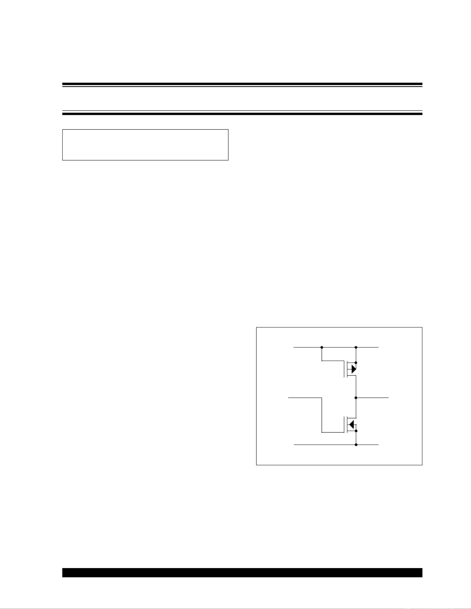
A simplified schematic for the MCP120 output stage is
shown in Figure 1. Nominally, the output stage of the
MCP120 can handle sinking less than 1 mA of current
in a high impedance state. That is, when the output is
not driving low and when a voltage is applied to the out-
put that is higher than the power supply level, the out-
put can handle sinking less than 1 mA. Other pertinent
electrical specifications for the device are shown in the
data sheet, which includes test conditions for the chip.
The MCP120 has an open drain output, though it is not
a true open drain. Specifically, the PMOS transistor on
the high side of the output stage is diode-connected, as
shown in Figure 1. When the voltage applied to the out-
put of the supervisor exceeds the power supply for the
chip, the PMOS transistor acts like a forward biased
diode. Lastly, since the output stage is open drain, a
pull-up resistor is required between the supervisor out-
put and VDD.
FIGURE 1: MCP120 output stage simplified.
Author: Ken Dietz
Microchip Technology Inc.
VDD
OutIn
GND
System Supervisors in ICSPTM Architectures
AN820
DS00820A-page 2 2002 Microchip Technology Inc.
ICSP Circuit Configuration
A schematic showing ICSP circuitry with the MCP120 is
shown in Figure 2. A current limiting resistor, RCL, limits
the current driven into the output stage of the supervisor
when the programming voltage is applied to the MCU.
A pull-up resistor, RPU, is placed between the supervi-
sor output and VDD, since the MCP120 output is open
drain and active low. Calculations for the resistors are
explained in the Design Methodology section.
The pull-down resistor, RPD, shown in Figure 2 is useful
during power-up and power-down sequences. Supervi-
sor functionality is not specified at power supply volt-
ages typically lower than 1 Volt, so the output stage of
the supervisor could be in a high impedance state. If
the supervisor output is high impedance and voltage is
applied to the MCU from an external source, the pro-
cessor could potentially run its program until the super-
visor takes over and resets the MCU again. This is
especially important in systems where multiple printed
circuit boards are interfaced together and a secondary
board might end up driving the MCU I/O pins before
power is applied to the primary board.
Since the voltage on the MCLR pin on a PICmicro®
MCU is very close to the power supply level, RPD can
be fairly large to minimize current consumption when
the circuit is normally operating. Furthermore, during
program and verify sequences, up to 13.25 Volts are
applied to the pull-down resistor. Because of this, R
PD
should also be large enough to minimize current con-
sumption for the programming voltage supply. A value
of 100 k (+/-5%) results in a maximum of 140 µA
when VPP is applied to the microcontroller, or 134 µA if
1% resistors are used, which is a small load for most
programmers. For battery powered applications, sub-
stantially larger valued resistors may be desirable for
this purpose.
FIGURE 2: Active low open drain ICSP circuit.
Key Programmer Specifications
The PRO MATE® II and the ICSP Socket Module, part
number AC004004, were used to test the circuit shown
in Figure 2. Current drive for the programming voltage
signal and current drive for the power supply signals are
critical specifications for the ICSP socket module. For
the VPP signal, the output of the ICSP module can pro-
vide as much as 100 mA, and for the power supply sig-
nal, the ICSP socket module can drive as much as
400 mA. Furthermore, the PRO MATE II programs
MCUs only at 5 Volts. However, it does have the capa-
bility to verify the memory contents of microcontrollers
at power supply levels ranging from 2.5 Volts to
5.5 Volts.
Another important aspect to consider for In-Circuit
Serial Programming includes the cable length for the
interface. Not only are sufficient current drive capabili-
ties required, but if a lengthy cable is used, reflections
and oscillations may cause programming errors.
Because of this phenomenon, manufacturers imple-
menting ICSP architectures should keep their cables
as short as possible. The circuits tested for the purpose
of this article implemented the ICSP cable that is nor-
mally shipped with the ICSP module, which is about 6
feet long. Lastly, the end of the cable connected to the
printed circuit board was modified to interface to a
modular connector.
VDD
(Programmer Supplied)
Bypass
Capacitor MCP120
VSS
VDD
RST
RPU RCL
3.3 Volts
Isolation
Microcontroller
VDD
MCLR
VSS
RPD
VPP


Produkt Specifikationer

Mærke: Microchip
Kategori: Ikke kategoriseret
Model: MCP111

Har du brug for hjælp?

Hvis du har brug for hjælp til Microchip MCP111 stil et spørgsmål nedenfor, og andre brugere vil svare dig


Ikke kategoriseret Microchip Manualer

Ikke kategoriseret Manualer

Nyeste Ikke kategoriseret Manualer