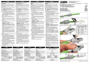
Phoenix Contact SUBCON-PLUS-PROFIB/PG/SC2 Manual

Phoenix Contact sensor SUBCON-PLUS-PROFIB/PG/SC2

Læs gratis den danske manual til Phoenix Contact SUBCON-PLUS-PROFIB/PG/SC2 (2 sider) i kategorien sensor. Denne vejledning er vurderet som hjælpsom af 21 personer og har en gennemsnitlig bedømmelse på 4.4 stjerner ud af 11 anmeldelser. Har du et spørgsmål om Phoenix Contact SUBCON-PLUS-PROFIB/PG/SC2, eller vil du spørge andre brugere om produktet?

Side 1/2
PHOENIX CONTACT GmbH & Co. KG
D-32823 Blomberg, Germany
Fax +49-(0)5235-341200, Tel. +49-(0)5235-300
MNR 9018274-01 / 08.2005
www.phoenixcontact.com
© PHOENIX CONTACT 2005
DEUTSCHENGLISHFRANÇAISESPAÑOL
1111
6666
7777
88
88
22
22
3333
5555
Abb./Fig. 1
44
44
1A 8
OFF S1
D(N)
390220 390Ω Ω
1B
2A
2B
3
5
6
D(P)
GND
VP
ON
Abb./Fig. 2
Abb./Fig. 4
6 5
13
24
[mm]
[inch]
0.512"
0.945"
0.197"0.236"
Abb./Fig. 3
Abb./Fig. 5
SUB-D-Stecker mit Schraubklemmenanschluss für PROFIBUS
SUB-D Plug With Screw Terminal Connection for PROFIBUS
Connecteur SUB-D à connexion à vis pour PROFIBUS
Conector SUB-D con conexión por tornillo para PROFIBUS
SUBCON-PLUS-PROFIB/SC2 Art.-Nr.: 27 08 23 2
SUBCON-PLUS-PROFIB/PG/SC2 Art.-Nr.: 27 08 24 5
DE
EN
FR
ES
SUBCONNEC-PLUS-PROFIB/SC2
SUBCONNEC-PLUS-PROFIB/PG/SC2
1. Description (Fig. 1)
1111 Partie supérieure du boîtier
2222 Interrupteur coulissant
33
33 Bloc de connexion
4444 Vis de fixation UNC
5555 Partie inférieure du boîtier
6666 Dispositif antitraction
77
77 Connecteur de contrôle
88
88 Vis du boîtier
Connecteur SUBCONNEC-PLUS-PROFIB/
SC2, avec ou sans connecteur de contrôle,
avec blocs de jonction à vis jusqu’à 12 Mbits/s.
Ce connecteur autorise un raccordement rapi-
de et convivial des segments de bus entrants et
sortants. Les contacts sont amenés sur des
blocs de jonction à vis disposés de façon claire
et avec un repérage en couleurs.
La résistance terminale connectable est
intégrée et déconnecte le segment sortant en
même temps qu’elle est activée (Fig.2). Cela
simplifie la mise en service du bus, qui peut se
faire par segment.
Le collier de blindage fixation
66
66, conçu pour le
câble profibus standard type A, est incorporé
dans le boîtier.
L’entrée de câble peut se faire, au choix, à droite
ou à gauche.
La version SUBCONNEC-PLUS-PROFIB/PG/
SC2 (Fig.1) comporte en plus un connecteur de
contrôle 7777 autorisant le raccordement d’un ap-
pareil de programmation ou de service, sans
interrompre le fonctionnement du bus.
2. Conseils pour le raccordement
Nous recommandons les outils à dénuder
suivants pour un dénudage rapide et conforta-
ble (Fig. 2) :
PSM-STRIP-FC/PROFIB (Réf. : 27 44 62 3)
et QUICK-WIREFOX 6 (Réf. : 12 04 38 4).
2.1. Longueurs à dénuder (Fig. 4)
Veuillez observer les longueurs à
dénuder recommandées pour un
fonctionnement sûr !
2.2. Introduction du câble
Avec le connecteur SUBCONNEC-PLUS-
PROFIB/... vous pouvez choisir d’introduire le
câble soit à droite soit à gauche.
Le connecteur est livré en standard avec entrée
de câble à gauche (Fig.5).
2.2.1. Raccordement
(pour entrée de câble à gauche)
(Fig.5)
Vissez les conducteurs dénudés dans les
contacts correspondants du bloc de connexion.
Le segment entrant doit toujours être raccor
aux connexions à borne 1A/1B (y compris au
début du bus !).
La ligne bus sortante doit toujours être con-
nectée aux connexions 2A/2B (voir Fig.2).
Veuillez prendre en compte l'impression en
couleur des blocs de jonction pour raccorde-
ment.
Montez et vissez la partie supérieure du
boîtier. A cet endroit on monte le dispositif
antitraction pour la ligne bus.
SUBCON-PLUS-PROFIB/SC2
SUBCON-PLUS-PROFIB/PG/SC2
1. Descripción (Fig. 1)
1111 Parte superior de caja
2222 Conmutador deslizante
33
33 Bloque de conexión
4444 Tornillo de fijación UNC
5555 Parte inferior de caja
6666 Compensador de tracción
77
77 Conexión para programación
88
88 Tornillo de caja
Conector SUBCON-PLUS-PROFIB/SC2 con y
sin conexión para programación, con conexión
por tornillo hasta 12 Mbits/s.
El conector permite la rápida y cómoda conexi-
ón del cable del bus de entrada y de continua-
ción. Los contactos del conector se han condu-
cido a bornes de conexión por tornillo
señalizados en color de buena identificación.
La resistencia terminal está integrada de forma
conectable y al activar, desconecta al mismo
tiempo la línea del bus de continuación (Fig.2).
Esto permite la puesta en servicio sencilla y por
segmentos del sistema bus.
El compensador de tracción 66
66 se p1-ha integrado
en la caja de dos piezas y se p1-ha dimensionado
para el cable estándar Profibus tipo A.
La introducción del cable se efectúa, opcional-
mente, por el lado derecha o el lado izquierda.
La conexión para programación integrada adici-
onal 77
77 de la variante SUBCON-PLUS-
PROFIB/PG/SC2 (Fig.1) facilita la conexión de
un aparato para programación o servicio, sin
interrumpir el funcionamiento del bus.
2. Instrucciones para la conexión
Para un rápido y cómodo desaislado se
recomienda utilizar los siguientes pelacables
(Fig. 2):
PSM-STRIP-FC/PROFIB (Código: 27 44 62 3) y
QUICK-WIREFOX 6 (Código: 12 04 38 4).
2.1. Longitudes a desaislar (Fig. 4)
Para obtener una función segura obser-
ve las longitudes a desaislar recomen-
dadas.
2.2. Introducción del cable
El conector SUBCON-PLUS-PROFIB/... ofrece
la posibilidad de elegir la introducción del cable
por el lado derecha o izquierda.
El conector se suministra confeccionado para
introducción por el lado izquierda (Fig.5).
2.2.1. Conexión (introducción del cable
por el lado izquierda)
(Fig.5)
Enrosque los conductores desaislados en los
contactos correspondientes del bloque de
conexión.
Conecte siempre la línea del bus de llegada
en las conexiones de borne 1A/1B (también
en el comienzo del sistema de bus).
La línea del bus de continuación se conecta
siempre en las conexiones de borne 2A/2B
(ver Fig.3).
A tal efecto, observe la impresión de color de
los bornes de conexión.
A continuación, monte y atornille las dos par-
tes de caja. De esta manera, se obtiene la
tracción compensada para la línea de bus.
SUBCON-PLUS-PROFIB/SC2
SUBCON-PLUS-PROFIB/PG/SC2
1. Description (Fig. 1)
1111 Upper shell of the housing
2222 Slide switch
33
33 Terminal block
4444 Mounting screw UNC
5555 Lower shell of the housing
6666 Strain relief
77
77 Programming connector
88
88 Housing screw
SUBCON-PLUS-PROFIB/SC2 plug with/
without programming connector, with screw
terminal block connection up to 12 Mbit/s.
The plug allows fast and convenient connection
of incoming and outgoing bus cables. Its con-
tacts are routed onto clearly color labeled
spring-cage terminal blocks.
The integrated terminal resistor can be connec-
ted and simultaneously disconnects the outgo-
ing bus cable when activating (Fig.2). This al-
lows an easy start up of the bus system one
segment at a time.
The strain relief
6666 is integrated in the housing
shells and is designed to hold a standard Profi-
bus cable type A.
The cable can be entered from either the left or
right.
The additionally integrated programming con-
tact 7777 of the SUBCON-PLUS-PROFIB/PG/
SC2 version (Fig.1) allows the connection of a
programming or service device without interrup-
ting bus operation.
2. Notes on Connecting
The following stripping tools are recommended
for fast and easy stripping (Fig. 3):
PSM-STRIP-FC/PROFIB (Order No.: 27 44 62 3)
and QUICK-WIREFOX 6 (Order No.: 12 04 38 4).
2.1. Stripping Lengths (Fig. 4)
To ensure reliable operation, observe the
recommended stripping!
2.2. Cable Entry
The
SUBCON-PLUS-PROFIB/... plug allows
the choice of cable entry from either the left or
right.
The plug is supplied pre-assembled for left-
hand entry (Fig.5).
2.2.1. Connection
(left-hand cable entry) (Fig.5)
Push the stripped conductor into the corre-
sponding contacts of the terminal block.
Always connect the incoming bus cable to the
connection points 1A/1B (also at the starting
point of the bus system!).
The outgoing bus cable is always connected
to terminal connections 2A/ 2B (see fig.2).
The color of the connection terminal blocks
labeling must then be observed.
To finish, mount the housing upper shell and
screw it together. This provides the strain re-
lief for the bus line.
SUBCON-PLUS-PROFIB/SC2
SUBCON-PLUS-PROFIB/PG/SC2
1. Beschreibung (Abb. 1)
1111 Gehäuseoberschale
2222 Schiebeschalter
33
33 Anschlussblock
4444 Befestigungsschraube UNC
5555 Gehäuseunterschale
6666 Zugentlastung
77
77 PG-Anschluss
88
88 Gehäuseschraube
SUBCON-PLUS-PROFIB/SC2-Stecker mit und
ohne PG-Anschluss, mit Schraubklemmenan-
schluss bis 12 MBit/s.
Der Stecker erlaubt den schnellen und komfor-
tablen Anschluss des ankommenden und wei-
terführenden Buskabels. Die Steckerkontakte
sind auf übersichtliche, farbig beschriftete
Schraubklemmen geführt.
Der Abschlusswiderstand ist zuschaltbar inte-
griert und schaltet beim Aktivieren gleichzeitig
die weiterführende Busleitung ab (Abb.2).
Dieses erlaubt die einfache und segmentweise
Inbetriebnahme des Bussystems.
Die Zugentlastung 66
66 ist in die Gehäusehalb-
schalen integriert und ist für das Standard-Pro-
fibuskabel Typ A ausgelegt.
Die Kabelzuführung erfolgt wahlweise von
rechts oder links.
Der zusätzlich integrierte Programmieran-
schluss 77
77 der SUBCON-PLUS-PROFIB/PG/
SC2-Variante (Abb.1) ermöglicht den An-
schluss eines Programmier- oder Service-Ge-
rätes, ohne den Bus-Betrieb zu unterbrechen.
2. Anschlusshinweise
Für eine schnelle und komfortable Abisolierung
werden folgende Abisolierwerkzeuge empfoh-
len (Abb. 3):
PSM-STRIP-FC/PROFIB (Art.-Nr.: 27 44 62 3)
und QUICK-WIREFOX 6 (Art.-Nr.: 12 04 38 4).
2.1. Abisolierlängen
(Abb.4)
Beachten Sie für eine sichere Funktion
die empfohlenen Abisolierlängen!
2.2. Kabelzuführung
Der SUBCON-PLUS-PROFIB/...-Stecker bietet
die Wahlmöglichkeit einer links- oder rechtssei-
tigen Kabelzuführung.
Bei Auslieferung ist der Stecker für linksseitige
Zuführung konfektioniert (Abb.5).
2.2.1. Anschluss
(linksseitige Kabelzuführung)
(Abb.5)
Verschrauben Sie die abisolierten Leiter in
den entsprechenden Kontakten des An-
schlussblocks.
Schließen Sie die ankommende Busleitung
immer an die Klemmenanschlüsse 1A/1B an
(auch am Anfang des Bussystems!).
Die weiterführende Busleitung wird immer an
die Klemmenanschlüsse 2A/2B angeschlos-
sen (siehe Abb.2).
Beachten Sie dabei die farbliche Bedruckung
der Anschlussklemmen.
Montieren und verschrauben Sie abschlie-
ßend die Gehäuseoberschale. Hierdurch wird
die Zugentlastung für die Busleitung aufge-
baut.
DEUTSCHENGLISHFRANÇAISESPAÑOL
2.2.2. Anschluss
(rechtsseitige Kabelzuführung)
(Abb.6)
Bei Bedarf einer rechtsseitigen Kabelzufüh-
rung ist die Leiterplatte mit Hilfe eines
Schraubendrehers im Bereich der Kabelein-
hrung aus der Gehäuseunterschale her-
auszuhebeln.
Legen Sie die Leiterplatte in die Gehäuseo-
berschale und verschrauben Sie die abiso-
lierten Leiter in den entsprechenden
Kontakten des Anschlussblocks.
Schließen Sie die ankommende Busleitung
immer an die Klemmenanschlüsse 1A/1B an
(auch am Anfang des Bussystems!).
Die weiterführende Busleitung wird immer an
die Klemmenanschlüsse 2A/2B angeschlos-
sen (siehe Abb.2).
Beachten Sie dabei die farbliche Bedruckung
der Anschlussklemmen.
Montieren und verschrauben Sie abschließend
die Gehäuseoberschale. Hierdurch wird die
Zugentlastung für die Busleitung aufgebaut.
3. Busabschlusswiderstand (Abb.7)
Abschlusswiderstand aktivieren und wei-
terführende Busleitungen abschalten:
Über den Schiebeschalter (2222 Abb.1) werden
am Anfang und Ende des Bussystems die Ab-
schlusswiderstände aktiviert. Gleichzeitig wer-
den die Anschlussklemmen (2A/2B) für die
weiterführende Busleitung abgeschaltet.
An allen anderen Knotenpunkten des Bus-
systems muss der Abschlusswiderstand
deaktiviert sein!
4. Technische Daten
Busleitung
Der Stecker ist für den Leitungstyp A nach
EN 50 170 spezifiziert.
Der ebenfalls in der EN 50 170 beschriebene
Leitungstyp B ist veraltet und sollte nicht mehr
verwendet werden.
Längenausdehnung gemäß PROFIBUS-
Spezifikation
Typ Artikel Nr.
SUBCON-PLUS-PROFIB/SC2
SUBCON-PLUS-PROFIB/PG/SC2
27 08 23 2
27 08 24 5
Steckeranschluss 9polige SUB-D
Stiftleiste
Programmieran-
schluss
9polige SUB-D
Buchsenleiste
Steckzyklen mind. 200
Kabeldurchmesser 8 mm (± 0,4 mm)
Befestigungsschrauben 4-40 UNC
max. Anzugsmoment 0,4 Nm
Gehäusematerial ABS, metallisiert
Temperaturbereich -20 °C bis +75 °C
Abmessungen siehe Abb. 8
Schraubanschluss
Anschlussquerschnitt
• starr
• flexibel
• AWG
0,14-1,5 mm2
0,14-1,0 mm2
26-16
Übertragungsgeschwin-
digkeit in kBit/s
zugehörige
Segmentlänge
9,6 / 19,2 / 45,45 / 93,75 1200 m
187,5 1000 m
500 400 m
1500 200 m
3000 / 6000 / 12000 100 m
2.2.2. Connection
(right-hand cable entry)
(Fig.6)
Should you require cable entry from the right,
lever the PCB out of the lower housing using
a screwdriver, inserting it in the vicinity of the
cable entry.
Lay the printed circuit board into the upper
shell of the housing and push the stripped
conductor into the corresponding contacts of
the terminal block.
Always connect the incoming bus cable to the
connection points 1A/1B (also at the starting
point of the bus system!).
The outgoing bus cable is always connected
to terminal connections 2A/ 2B (see fig.2).
The color of the connection terminal blocks
labeling must then be observed.
To finish, mount the housing upper shell and
screw it together. This provides the strain
relief for the bus line.
3. Bus Terminating Resistor (Fig.7)
Activating terminating resistor and swit-
ching off outgoing bus cables:
The terminating resistors are activated via the
slide switch (22
22 Fig.1) at the starting and final
point of the bus system. At the same time the
connection points (2A/2B) for the outgoing bus
cable are switched off.
At all other nodes of the bus system the
corresponding terminating resistor must be
deactivated!
4. Technical Data
Bus cable
The plug is specified for cable type A according
to EN 50 170.
Cable type B, also described in EN 50 170, is
outdated and must not be used anymore.
Linear extension acc. to the PROFIBUS
specification
Type Order No.
SUBCON-PLUS-PROFIB/SC2
SUBCON-PLUS-PROFIB/PG/SC2
27 08 23 2
27 08 24 5
Plug connection 9-pos. SUB-D male
connector
Programming connec-
tion
9-pos. SUB-D female
connector
Insertion / withdrawal min. 200
Cable cross section 8 mm (± 0.4 mm)
Mounting screws 4-40 UNC
Max. torque 0.4 Nm
Housing material ABS, metal-plated
Temperature range -20°C to +75°C
Dimensions see fig. 8
Screw terminal connection
Connection cross section
• rigid
• flexible
• AWG
0.14-1.5 mm2
0.14-1.0 mm2
26-16
Transmission rate in kbit/s corresponding
segment length
9.6 / 19.2 / 45.45 / 93.75 1,200 m
187.5 1,000 m
500 400 m
1500 200 m
3000 / 6000 / 12000 100 m
2.2.2. Raccordement
(pour entrée de câble à droite)
(Fig.6)
Si vous devez introduire le câble du côté droit,
il faut faire levier sur le circuit imprimé à l’aide
d’un tournevis au niveau d’entrée de câble
pour le sortir de la moitié inférieure du boîtier.
Posez ensuite le circuit imprimé dans la moitié
supérieure du boîtier et vissez les conducteurs
nudés dans les contacts correspondants du
bloc de connexion.
Le segment entrant doit toujours être raccor
aux connexions à borne 1A/1B (y compris au
début du bus !).
La ligne bus sortante doit toujours être con-
nectée aux connexions 2A/2B (voir Fig.2).
Veuillez prendre en compte l'impression en
couleur des blocs de jonction pour raccorde-
ment.
Montez et vissez la partie supérieure du
boîtier. A cet endroit on monte le dispositif
antitraction pour la ligne bus.
3. Résistance terminale du bus (Fig.7)
Activer la résistance terminale et déconnec-
ter les segments de bus sortants :
L’interrupteur coulissant (
2222 Fig.1) permet
d’activer les résistances terminales situées aux
extrémités du bus. Simultanément, les bornes
de connexion (2A/2B) pour le segment suivant
sont déconnectées.
Les résistances terminales de tous les
autres nœuds de la ligne doivent être
déconnectées !
4. Caractéristiques techniques
Câble du bus
Ce connecteur est spécifié pour le câble type A
selon EN 50 170.
Le câble type B, également décrit dans la nor-
me EN 50 170, est obsolète et ne devrait plus
être utilisé.
Longueur autorisée selon la spécification
PROFIBUS
Type Référence
SUBCONNEC-PLUS-PROFIB/SC2
SUBCONNEC-PLUS-PROFIB/PG/SC2
27 08 23 2
27 08 24 5
Raccord. connecteur Connecteur SUB-D
mâle 9 pôles
Raccord. programma-
teur
Connecteur SUB-D
femelle 9 pôles
Nbre cycles d’enfichage 200 minimum
Diamètre du câble 8 mm (± 0,4 mm)
Vis de fixation 4-40 UNC
Couple serrage max. 0,4 Nm
Matériau du boîtier ABS, métalli
Plage de température -20 °C à +75 °C
Dimensions voir Fig. 8
Connexion vissée
Section raccordable
• rigide
• souple
• AWG
0,14-1,5 mm2
0,14-1,0 mm2
26-16
Vitesse transmission en
kbits/s
Longueur
correspondante
des segments
9,6 / 19,2 / 45,45 / 93,75 1200 m
187,5 1000 m
500 400 m
1500 200 m
3000 / 6000 / 12000 100 m
2.2.2. Conexión (introducción del cable
por el lado derecha) (Fig.6)
Si se necesita una introducción del cable por
el lado derecha, con ayuda de un destornilla-
dor apalánque la placa de circuito impreso en
la cercanía de la introducción del cable hacia
afuera de la parte inferior de caja
Coloque la placa de circuito impreso en la
parte superior de caja y enrosque los con-
ductores desaislados en los contactos corre-
spondientes del bloque de conexión.
Conecte siempre la línea del bus de llegada
en las conexiones de borne 1A/1B (también
en el comienzo del sistema de bus).
La línea del bus de continuación se conecta
siempre en las conexiones de borne 2A/2B
(ver Fig.2). A tal efecto, observe la impresión
de color de los bornes de conexión.
A continuación, monte y atornille las dos par-
tes de caja. De esta manera, se obtiene la
tracción compensada para la línea de bus.
3. Resistencia terminal del bus (Fig.7)
Activar la resistencia terminal y desconec-
tar las líneas del bus de continuación:
Mediante el conmutador deslizante (2222 Fig.1)
se activan las resistencias terminales al comien-
zo y final del sistema de bus. Al mismo tiempo,
los bornes de conexión (2A/2B) se desconectan
para la línea del bus de continuación.
¡En todos los otros nudos del sistema de
bus la resistencia terminal tiene que estar
desactivada!
4. Datos técnicos
Línea de bus
El conector está especificado para el tipo de
cable A según EN 50 170.
El tipo de cable B, igualmente descrito en la
EN 50 170 es antiguado y no debe utilizarse.
Extensión de línea según especificación
PROFIBUS
Referencia Código
SUBCON-PLUS-PROFIB/SC2
SUBCON-PLUS-PROFIB/PG/SC2
27 08 23 2
27 08 24 5
Conexión conector conector macho
SUB-D 9 polos
Conexn para pro-
gramar
conector hembra
SUB-D 9 polos
Ciclos de enchufe mínimo 200
Diámetro de cable 8 mm (± 0,4 mm)
Tornillos de fijación 4-40 UNC
par de apriete máx. 0,4 Nm
Aislamiento caja ABS, metalizada
Gama de temperatura -20 °C hasta +75 °C
Dimensiones ver Fig. 8
Conexión por tornillo
Sección de conexión
• rígido
• flexible
• AWG
0,14-1,5 mm
2
0,14-1,0 mm
2
26-16
Velocidad de transmisión
en kbits/s
Longitud de
segmento
correspondiente
9,6 / 19,2 / 45,45 / 93,75 1200 m
187,5 1000 m
500 400 m
1500 200 m
3000 / 6000 / 12000 100 m
5 8
3 5
3 5 , 5 1 6 , 6
3 9 , 4
Abb./Fig. 8
[mm]
[inch]
0.654"1.398"
1.378"
2.284"
1.551"
Abb./Fig. 6
ON ON
OFFOFFOFFOFF
Abb./Fig. 7
Anfang
Start
Début
Comienzo
Ende
End
Fin
Final


Produkt Specifikationer

Mærke: Phoenix Contact
Kategori: sensor
Model: SUBCON-PLUS-PROFIB/PG/SC2
Bredde: 16.6 mm
Dybde: 58 mm
Højde: 39.4 mm
Vægt: 48.8 g
Produktfarve: Metallic
Strøm: 0.1 A
Opbevaringstemperatur (T-T): -20 - 80 °C
Driftstemperatur (T-T): -20 - 75 °C
Dimensioner (BxDxH): 16.6 x 58 x 39.4 mm
Materiale: Acrylonitrile butadiene styrene (ABS), Metal
Certificering: UL / cUL / CSA / EAC
Bæredygtighedscertifikater: RoHS
Stik: D-SUB
Spænding: 5 V
Kabeldiameter: 8.4 mm
Isolationsmodstand: 390 mΩ

Har du brug for hjælp?

Hvis du har brug for hjælp til Phoenix Contact SUBCON-PLUS-PROFIB/PG/SC2 stil et spørgsmål nedenfor, og andre brugere vil svare dig