Phoenix Contact VS-08-RJ45-5-Q/IP67 Manual
Phoenix Contact
sensor
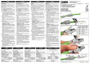
VS-08-RJ45-5-Q/IP67

| Mærke: | Phoenix Contact |
| Kategori: | sensor |
| Model: | VS-08-RJ45-5-Q/IP67 |
Har du brug for hjælp?
Hvis du har brug for hjælp til Phoenix Contact VS-08-RJ45-5-Q/IP67 stil et spørgsmål nedenfor, og andre brugere vil svare dig
sensor Phoenix Contact Manualer
9 September 2025

1 December 2024

1 December 2024

1 December 2024

1 December 2024

1 December 2024

1 December 2024

1 December 2024
sensor Manualer
- Hikvision
- Vimar
- LiftMaster
- IFM
- Crestron
- JUNG
- Bosch
- Homematic IP
- Panasonic
- Schwaiger
- Weidmüller
- Heatit
- Moen
- Sensirion
- Kemo
Nyeste sensor Manualer

14 September 2025

13 September 2025

13 September 2025

13 September 2025
27 August 2025
20 August 2025
20 August 2025
19 August 2025
18 August 2025
18 August 2025