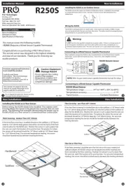
Pro1 R250S Manual


Læs gratis den danske manual til Pro1 R250S (2 sider) i kategorien Ikke kategoriseret. Denne vejledning er vurderet som hjælpsom af 3 personer og har en gennemsnitlig bedømmelse på 4.3 stjerner ud af 2 anmeldelser. Har du et spørgsmål om Pro1 R250S, eller vil du spørge andre brugere om produktet?

Side 1/2
R250S
Installation Manual
Pro1 Technologies
P.O. Box 3377
Springeld, MO 65804
Toll Free : 888-776-1427
Web: www.pro1iaq.com
Hours of Operation: M-F 9AM - 6PM Eastern
Table of Contents
New Installations
Resistance Chart
Specications & Warranty
Page
Una version en espanol de este
manual se puede descargar en la
pagina web de la compania.
Rev. 1807
New Installations
6
7
2-5
New Installations New Installations
Connecting to a Wired Sensor Capable Thermostat
Before wiring, the R250S needs to be installed. The stainless steel
housing allows this sensor to be placed into concrete, thin-set, and
grout. The following ve examples demonstrate the proper way to
install a R250S as a oor sensor in conventional oor construction.
Installing the R250S as a Floor Sensor
Do not operate the cooling
system if the outdoor
temperature is below 50˚F
(10˚ C) to prevent possible
compressor damage.
Caution: Equipment
Damage Hazard
U.S. Registered Trademark. Patents pending
Copyright 2018 All Rights Reserved.
This manual covers the following models:
• R250S (Requires a Wired Sensor Capable Thermostat)
Congratulations on purchasing a PRO1 Wired Sensor.
This remote sensor was designed to the highest reliability
and ease of use standards. Thank you for choosing our
quality products
Thick Covering - Greater Than 3/8” (10mm)
If the thick oor covering is installed directly to the suboor, a 1/8” (4mm)
wide by 1/16” (2mm) deep groove should be cut into the back of the oor
cover to allow for the R250S wire. Position the sensor in such a place that
the wire can reach the location of its junction box. The groove for where
the sensor will be placed should be 1/4” (8mm) wide by 1/4” (8mm) deep
by 1 3/4” (45mm) long. For accurate temperature reading, the sensor
should be located exactly between heating elements.
Subfloor
Hardwood
Thin Covering - Less Than 3/8” (10mm)
If the thin oor covering is installed directly to the suboor, a 1/8” (4mm) wide
by 1/16” (2mm) deep groove should be cut into the surface of the suboor to
allow for the R250S wire. Position the sensor in such a place that the wire can
reach the location of its junction box. The groove for where the sensor will
be placed should be 1/4” (8mm) deep by 1 3/4” (45mm) long. For accurate
temperature reading the sensor should be located exactly between the
heating elements.
Subfloor
Hardwood
Thin-Set or Thin-Pour
If the oor covering is installed over the thin-set or thin-pour material of
sucient depth, the R250S sensor can be placed into either material and
then covered by the oor covering. Position the sensor in such a place that
the wire can reach the location of its junction box. For accurate temperature
reading, the sensor should be located exactly between the heating elements.
Tile
Thin-Se t
Electric Heat
Installing the R250S as an Outdoor Sensor
The R250S can also be used as an Outdoor Temperature Sensor. Included in the package
is a metal wall mount and 2 screws. Securely screw the mount with the R250S into a
shaded area.
Wiring the R250S
The R250S is packaged with 6’ of 1.8mm cable. If you need more length, 24 AWG or larger
wire can be joined onto the two wires from the sensor. The splices need to be properly joined
and protected in an accessible junction box.
Do NOT run the wires parallel to telephone or power cables. If there is a strong source of
electromagnetic interference near the location of the sensor wires, a twisted pair or a
protected cable should be used. The wires can also be run in a grounded metal conduit.
Warning:
After installation connect the R250S to the S terminal blocks on the Wired Sensor Capable
Thermostat. Loosen the terminal block screws. Insert wires, then retighten terminal
block screws.
R250S Remote Sensor
NOTE: Refer to your wred sensor capable thermostat manual for setup
Connecting to a Wired Sensor Capable Thermostat
R250S Wired Sensor
Temperature range................... -4ºF to 140ºF (-20ºC to 60ºC)
Temperature accuracy............................................................± 1ºF
Transmission................................................Constant Resistance
A trained, experienced technician
must install this product.
Carefully read these
instructions. You could damage
this product or cause a
hazardous condition if you fail to
follow these instructions.
S1
S2
New Installations Resistence Chart
41303113 45.00
115 46.11 39434
117 47.22 37660
119 48.33 35976
121 49.44 34376
123 50.56 32843
125 51.67 31399
127 52.78 30027
129 53.89 28722
131 55.00 27481
133 56.11 26300
135 57.22 25177
137 58.33 24107
139 59.44 23089
141 60.56 22111
143 61.67 21188
145 62.78 20308
147 63.89 19469
149 65.00 18670
151 66.11 17907
153 67.22 17180
155 68.33 16486
157 69.44 15824
159 70.56 15187
161 71.67 14584
163 72.78 14008
165 73.89 13458
167 75.00 12932
169 76.11 12430
171 77.22 11949
173 78.33 11490
175 79.44 11051
177 80.56 10627
179 81.67 10225
181 82.78 9841
183 83.89 9473
185 85.00 9121
187 86.11 8783
-39- 39.44 3916295
-37- 38.33 3627711
-35- 37.22 3362274
-33- 36.11 3117987
-31- 35.00 2893035
-29- 33.89 2685770
-27- 32.78 2494694
-25- 31.67 2318444
-23- 30.56 2155781
-21- 29.44 2004274
-19- 28.33 1865595
-17- 27.22 1737397
-15- 26.11 1618827
-13- 25.00 1509102
-11- 23.89 1407512
-9 -22.78 1313405
-7 -21.67 1226184
-5 -20.56 1145306
-3 -19.44 1069620
-1 -18.33 1000019
1- 17.22 935383
3- 16.11 875329
5- 15.00 819505
7- 13.89 767589
9- 12.78 719284
11 -11.67 674319
13 -10.56 632442
15 -9.44 593086
17 -8.33 556739
19 -7.22 522842
21 -6.11 491217
23 -5.00 461699
25 -3.89 434134
27 -2.78 408383
29 -1.67 384316
31 -0.56 361813
33 0.56 340581
35 1.67 320895
°F C Ohms
°F C Ohms
°F C Ohms
37 2.78 302466
39 3.89 285206
41 5.00 269035
43 6.11 253877
45 7.22 239664
47 8.33 226331
49 9.44 213819
51 10.56 201971
53 11.67 190946
55 12.78 180588
57 13.89 170853
59 15.00 161700
61 16.11 153092
63 17.22 144992
65 18.33 137367
67 19.44 130189
69 20.56 123368
71 21.67 117000
73 22.78 110998
75 23.89 105338
77 25.00 100000
79 26.11 94963
81 27.22 90208
83 28.33 85719
85 29.44 81479
87 30.56 77438
89 31.67 73654
91 32.78 70076
93 33.89 66692
95 35.00 63491
97 36.11 60461
99 37.22 57594
101 38.33 54878
103 39.44 52306
105 40.56 49847
107 41.67 47538
109 42.78 45349
111 43.89 43273
100K Thermistor Output Table
Specications
Operating Temperature ...................... 32˚F to 105˚F (0˚C to +41C)
Operating humidity............................... 90% non-condensing maximum
Dimensions of sensor .......................... 1.5W x 2.75”H x 0.75”D
Resistance range ...................................Up to 300 feet
Warranty Registration
Your new thermostat has a 5 year limited warranty. You must register
your thermostat within 60 days of installation. Without this
registration the warranty period will begin on date of manufacture.
For warranty issues please contact the HVAC professional that
installed this product. You can register your new thermostat in 2 ways:
Go to the company website, select warranty registration and
ll out a short registration form.
Complete the form below and mail it to the address shown.
Warranty Registration
Online
Mail
Name:
Address:
City:
State:
Zip:
Thermostat Model:
Date Installed:
Complete form and mail to:
Thermostat Warranty Registration
Installing to the bottom of the suboor
If installing the R250S sensor to the bottom of the suboor, cut a piece of 1”
(25mm) thick insulation into a 6” (150mm) by 6” (150mm) square. A 1/4” (8mm)
wide by 1/4” (8mm) deep by 1 3/4” (45mm) long groove should be cut into the
insulation to allow for the sensor. Position the sensor in such a place that the
wire can reach the location of its junction box. Use a preferred and eective
method to fasten the insulation to the suboor.
Tile Flooring
The R250S sensor can be installed into existing tile with adequate grout lines.
Select a location for the sensor that is exactly between the heating elements
and in a low trac area. Position the sensor in such a place that the wire can
Subfloor
Insulatio n
Tile
Thin-Se t
Subfloor
Specications & Warranty
P.O. Box 3377
Springeld, MO 65804


Produkt Specifikationer

Mærke: Pro1
Kategori: Ikke kategoriseret
Model: R250S

Har du brug for hjælp?

Hvis du har brug for hjælp til Pro1 R250S stil et spørgsmål nedenfor, og andre brugere vil svare dig


Ikke kategoriseret Pro1 Manualer
Pro1

Pro1 T501ML4 Manual

17 September 2025
Pro1

Pro1 R250S Manual

16 September 2025

Ikke kategoriseret Manualer

Nyeste Ikke kategoriseret Manualer

Blodgett

Blodgett Invoq 61BG Manual

17 September 2025
Vestil

Vestil LAD-FM-84-PSO Manual

17 September 2025
Vestil

Vestil PLC-P-FM Manual

17 September 2025
Berker

Berker 85606100 Manual

17 September 2025
KStrong

KStrong UFS310010 Manual

17 September 2025
Vestil

Vestil H-100-LD Manual

17 September 2025
Wesco

Wesco 272938 Manual

17 September 2025
Texican

Texican TCD-1AL Manual

17 September 2025
Vestil

Vestil WTJ-2 Manual

17 September 2025