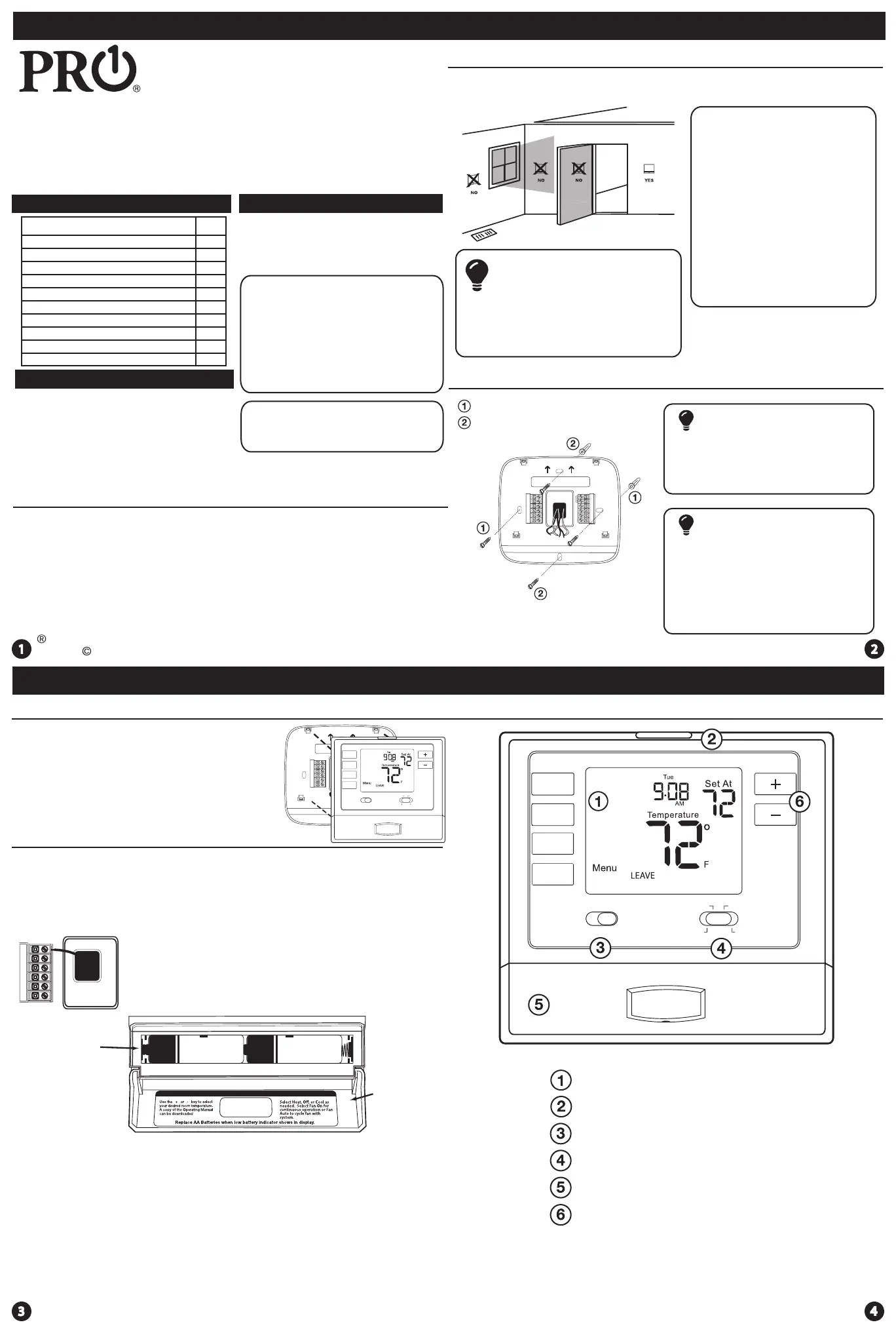
Pro1 T725 Manual


Læs gratis den danske manual til Pro1 T725 (4 sider) i kategorien Ikke kategoriseret. Denne vejledning er vurderet som hjælpsom af 3 personer og har en gennemsnitlig bedømmelse på 4.8 stjerner ud af 2 anmeldelser. Har du et spørgsmål om Pro1 T725, eller vil du spørge andre brugere om produktet?

Side 1/4
T725
Installation Manual
Pro1 Technologies
Toll Free: 888-776-1427
Web: www.pro1iaq.com
Hours of Operation: M-F 9AM - 6PM Eastern
Power Type
Battery Power
Hardwire (Common Wire)
Hardwire (Common Wire) with
Battery Backup
A trained, experienced
technician must install this
product.
Carefully read these
instructions. You could damage
this product or cause a
hazardous condition if you fail to
follow these instructions.
Una version en español de este
manual se puede descargar en
la pagina web de la compañia.
Rev. 1751
U.S. Registered Trademark. Patents pending
Copyright 2017 All Rights Reserved.
Installation Tips
Installation Tips
Thermostat Application Guide
Table of Contents
Installation Tips
Thermostat Quick Reference
Wiring
Wiring Diagrams
Features & About The Badge
Technician Setup
Programming Thermostat
Page
2-3
4-5
6
7
8
13-16
Subbase Installation
The thermostat should be installed approximately 4 to 5 feet above the
oor. Select an area with average temperature and good air circulation.
• Close to hot or cold air ducts
That are in direct sunlight
With an outside wall behind
the thermostat
• In areas that do not require
conditioning
Where there are dead spots
or drafts
(in corners or behind doors)
Where there might be
concealed chimneys or
pipes
Wall Locations
Vertical Mount
Horizontal Mount
For vertical mount put one screw on the top
and one screw on the bottom.
For horizontal mount put one screw on the
left and one screw on the right.
All of our products are mercury free.
However, if the product you are
replacing contains mercury, dispose of
it properly. Your local waste
management authority can give you
instructions on recycling and proper
disposal.
Pick an installation location that is easy for
the user to access. The temperature of the
location should be representative of the
building.
Installation Tip
Mercury Notice
Do not install
thermostat in locations:
Failure to disconnect the power before
beginning to install this product can
cause electrical shock or equipment
damage.
Installation Tip:
Electrical Hazard
Mount Thermostat
Align the 4 tabs on the subbase with
corresponding slots on the back of the
thermostat, then push gently until the
thermostat snaps in place.
Battery Installation
Battery installation is recommended even if thermostat is hardwired
(C terminal connected). When thermostat is hardwired and batteries
are installed, the thermostat will activate a compressor delay of 5
minutes when the thermostat detects a power outage from the
hardwired power supply.
Important:
High quality alkaline batteries are recommended.
Rechargeable batteries or low quality batteries
do not guarantee a 1-year life span.
Insert 2 AA
Alkaline batteries
(included). High
quality alkaline
batteries are
recommended.
Simple
operating
instructions
are found
on the back
of the
battery
door.
Getting to know your thermostat
Glow in the dark light button
Fan Switch
System Switch
Easy change battery door
Temperature Setpoint Buttons
LCD Display
Thermostat Quick Reference
Specications
The display range of temperature ... 41˚F to 95˚F (5˚C to 35˚C)
The control range of temperature.... 44˚F to 90˚F (7˚C to 32˚C)
Swing (cycle rate or dierential) ...... Heating is adjustable from 0.2˚ to 2.0˚
Cooling is adjustable from 0.2˚ to 2.0˚
Power source ...........................................18 to 30 VAC, NEC Class II, 50/60 Hz
for hardwire
Battery power from 2 AA Alkaline
batteries
Operating ambient ............................... 32˚F to +105˚F (0˚C to +41˚C)
Operating humidity .............................. 90% non-condensing maximum
Dimensions of thermostat ................. 4.7”W x 4.4”H x 0.8”D
9 -12
Description
Gas or Oil Heat
Electric Furnace
Heat Pump (No Aux. or Emergency Heat)
Heat Pump (With Aux. or Emergency Heat)
Multi-Stage Systems
Heat Only Systems
Heat Only Systems - Floor or Wall Furnace
Cool Only Systems
Millivolt Conventional Systems
Yes
Yes
Yes
Yes
Yes
Yes
Yes
Yes
Yes
Two Transformer Systems No
FAN
ON AUTO
EmHCOOL
OFF HEAT
FAN
ON AUTO
EmHCOOL
OFF HEAT
P.O. Box 3377
Springeld, MO 65808-3377
Thermostat Quick Reference
Wiring
Tech Settings Tech Settings
This thermostat has a technician setup menu for easy installer
conguration. To setup the thermostat for your particular application:
Swing Setting Tip
Temperature swing, sometimes called dierential or cycle rate, can be customized
for this individual application. For most applications choose a swing setting that is
as long as possible without making the occupants uncomfortable.
Technician Setup Menu
LCD Will Show
The compressor short cycle delay
protects the compressor from
short cycling. This feature will not
allow the compressor to be turned
on for 5 minutes after it was last
turned o.
Selecting “ON” will not allow
the compressor to be turned on
for 5 minutes after the last time
the compressor was switched
o. Select “OFF” to remove this
delay.
0
This feature allows the installer
to change the calibration of the
room temperature display. For
example, if the thermostat reads
70˚ degrees and you would like it
to read 72˚ then select +2.
Room
Temperature
Calibration
You can adjust the room
temperature display to read
4˚above or below the factory
calibrated reading.
Tech Settings
Adjustment Options
Compressor
Short Cycle
Delay
Default
0N
Cd
0.8
The swing setting often called
cycle rate, “dierential” or “
anticipation is adjustable. A
smaller swing setting will cause
more frequent cycles and a larger
swing setting will cause fewer
cycles.
Cooling
Swing
The cooling swing setting is
adjustable from 0.2˚ to 2˚. For
example: A swing setting of
0.5˚ will turn the cooling on at
approximately 0.5˚ above the
setpoint and turn the cooling
o at approximately 0.5˚ below
the setpoint.
0FF
This feature will ash “FILT” in the
display after the elapsed run time
to remind the user to change the
lter. A setting of “OFF” will disable
this feature.
Filter Change
Reminder
You can adjust the lter change
reminder from OFF to 2000
hours of runtime in 50 hour
increments.Tap the second
button from the top left side of
the thermostat to display the
current lter elapsed runtime.
F1
Next Step
Prev Step
100
SE
0
Next Step
Prev Step
CAL
Next Step
Prev Step
Next Step
Prev Step
Use the or keys to change settings and the NEXT STEP or
PREV STEP key to move from one step to another. Note: Only press
the DONE key when you want to exit the Technician Setup options.
1. Press the MENU button
2. Press and hold TECH SET button for 3 seconds. This 3 second
delay is designed so that homeowners do not accidentally access
the installer settings.
3. Congure the installer options as desired using the table below.
Tech Settings
Adjustment Options Default
The swing setting often called cycle
rate, “dierential” or “anticipation”
is adjustable. A smaller swing
setting will cause more frequent
cycles and a larger swing setting
will cause fewer cycles.
The heating swing setting is
adjustable from 0.2˚ to 2˚. For
example: A swing setting of
0.5˚ will turn the heating on at
approximately 0.5˚ below the
setpoint and turn the heating
o at approximately 0.5˚ above
the setpoint.
Heating
Swing
0.8
Next Step
Prev Step
This feature allows you to set a
minimum cool setpoint value. The
setpoint temperature cannot be
lowered below this value.
Cooling
Setpoint
Limit
44
Use the and key to
select the minimum cool
setpoint.
This feature allows you to set a
maximum heat setpoint value. The
setpoint temperature cannot be
raised above this value.
Heating
Setpoint
Limit
90
Use the and key to
select the maximum heat
setpoint.
Next Step
Prev Step
Next Step
Prev Step
CO L
Select F for Fahenheit temperature
read out or select C for Celsius
read out.
F for Fahrenheit
C for Celsius
F or C
F
F
FC
You can select either a 12 or 24 hour
clock setting.
12 or 24
Hour Clock
12
Use the and to select 12
or 24 hour clock.
Next Step
Prev Step
Next Step
Prev Step
HE L
dFHE
LCD Will Show
The low battery indicator is displayed when the AA battery power is low. If the user
fails to replace the battery within 21 days, the screen will only show the low battery
indicator but maintain all functionality. If the user fails to replace the batteries after
an additional 21 days (days 22-42 since rst “low battery display) the setpoints will
change to 55˚F (Heating) and 85˚F (Cooling). If the user adjusts the setpoint away from
either of these, it will hold for 4 hours then return to either 55˚F or 85˚F. After day 63
the batteries must be replaced immediately to avoid freezing or overheating because
the thermostat will shut the unit o until the batteries are changed.
Important
Indicates the current room temperature
Time and day of the week
Setpoint: Displays the user selectable setpoint temperature.
Hold is displayed when the thermostat program is permanently overridden.
System Operation Indicators:
The COOL ON, HEAT ON or icon will display when the COOL, HEAT, or (fan) is on.
Note: The Compressor delay feature is active if these are ashing.
Low Battery Indicator: Replace batteries when this indicator is shown.
Button Options
Program Time Periods: This thermostat has 4 programmable time periods
per day.
Getting to know your thermostat
Hold
LOW
COOL ON
EmHEAT ON
Sun Mon Tue Wed Thu Fri Sat
Temperature
Tech Set
Next Step
Set Time
Run Sched
Set Sched
Hold
Prev Step
Menu
Done
LEAVE SLEEP
RETURN WAKE
Stage 1 & 2
Stages: Indicates the stages of heat that are active.
Caution:
Electrical Hazard
All components of the
control system and the
thermostat installation must
conform to Class II circuits
per the NEC Code.
Warning:
Do not overtighten terminal
block screws, as this can
damage the terminal block.
A damaged terminal block
can keep the thermostat
from tting on the subbase
correctly or cause system
operation issues.
Installation Tip
Max Torque = 6in-lbs.
Wiring
If you are replacing a thermostat,
make note of the terminal
connections on the thermostat
that is being replaced. In some
cases the wiring connections will
not be color coded. For example,
the green wire may not be
connected to the G terminal.
Loosen the terminal block
screws. Insert wires then
retighten terminal block screws.
Place nonammable insulation
into wall opening to prevent
drafts.
1.
2.
3.
Terminal Designations
R
Failure to disconnect the power
before beginning to install this
product can cause electrical
shock or equipment damage.
C
B
O
G
W/E
W2
Y
Heat Pump System
1 HEAT 1 COOL / 2 HEAT 1 COOL
Conventional System
1 HEAT 1 COOL / 2 HEAT 1 COOL
Transformer Power
Transformer Common
Changeover Valve
Energized in HEAT
Fan Relay
First Stage of Emergency HEAT
Changeover Valve
Energized in COOL
Second Stage of HEAT/
EMERGENCY HEAT
First Stage of HEAT and COOL
Transformer Power
Transformer Common
Fan Relay
First Stage of HEAT
Second Stage of HEAT
First Stage of COOL
Energized in HEAT
Energized in COOL
1
2
3
7
8
1
3
2
7
8


Produkt Specifikationer

Mærke: Pro1
Kategori: Ikke kategoriseret
Model: T725

Har du brug for hjælp?

Hvis du har brug for hjælp til Pro1 T725 stil et spørgsmål nedenfor, og andre brugere vil svare dig


Ikke kategoriseret Pro1 Manualer

Pro1

Pro1 T725 Manual

17 September 2025
Pro1

Pro1 T501ML4 Manual

17 September 2025
Pro1

Pro1 R250S Manual

16 September 2025

Ikke kategoriseret Manualer

Nyeste Ikke kategoriseret Manualer

Vestil

Vestil WTJ-20-4-DC Manual

17 September 2025
Canarm

Canarm CNP100 Manual

17 September 2025
Vestil

Vestil FPG-3 Manual

17 September 2025
Vestil

Vestil BOL-42-5.5 Manual

17 September 2025
Turbo Air

Turbo Air M3H24-1-TS Manual

17 September 2025
Dry Ager

Dry Ager UX1500 PRO Manual

17 September 2025
Vestil

Vestil IBC-TLT Manual

17 September 2025
Vestil

Vestil LAD-FM-96 Manual

17 September 2025
Vestil

Vestil FHS-4-10 Manual

17 September 2025
DeLOCK

DeLOCK 91758 Manual

17 September 2025