Puls Dimension DIMENSION UBC10.241-N1 Manual

Puls Dimension UPS DIMENSION UBC10.241-N1

Læs gratis den danske manual til Puls Dimension DIMENSION UBC10.241-N1 (23 sider) i kategorien UPS. Denne vejledning er vurderet som hjælpsom af 44 personer og har en gennemsnitlig bedømmelse på 4.6 stjerner ud af 22.5 anmeldelser. Har du et spørgsmål om Puls Dimension DIMENSION UBC10.241-N1, eller vil du spørge andre brugere om produktet?

Side 1/23
UBC10.241, UBC10.241-N1
USeries
24V, 10A, DC-UPS
1/23
DC-UPS WITH INTEGRATED BATTERY
Compact and Easy to Install
Longest Buffer Time in Class
Easy Battery Access
Stable Output Voltage in Buffer Mode
Superior Battery Management for Longest Battery Life
Temperature Compensated Battery Charging
Comprehensive Diagnostics and Monitoring Functions
Replace Battery Signal Included
Electronically Overload and Short Circuit Protected
50% Power Reserves
Selectable Buffer Time Limiter
1. GENERAL DESCRIPTION
2. SHORT-FORM DATA
Input voltage nom. 24Vdc
range 22.5-30Vdc
Output current min. 15A Normal mode
min. 10A Buffer mode
Output voltage typ. 0.23V lower
as input voltage
Normal mode
22.25V Buffer mode, 10A
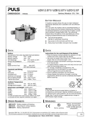
Integrated battery 12V 5Ah VRLA lead acid
Temperature range 0 to 40°C Operational
Dimensions 123x124x119mm WxHxD
Buffer time typ. 16’15” At 5A load
typ. 6’15” At 10A load
This uninterruptible power supply (UPS) controller
UBC10.241 with integrated battery is a compact
addition to standard 24V power supplies to bridge
power failures or voltage fluctuations. Expensive
downtimes, long restart cycles and loss of data can
be avoided.
The DC-UPS includes a professional battery
management system which charges and monitors
the battery to achieve the longest battery service life
as well as many diagnostic functions that ensure a
reliable operation of the entire system.
A unique feature of the UBC10.241 is that only one
12V battery is required to buffer the 24V output.
This makes matching batteries unnecessary and
allows a precise battery charging and testing.
The UBC10.241 has one integrated 12V 5Ah high
current VRLA battery, which is easy to change.
In addition to the UBC10.241, a separate UPS
controller (UB10.241) which requires an external 12V
battery is available when a longer buffer time is
required.
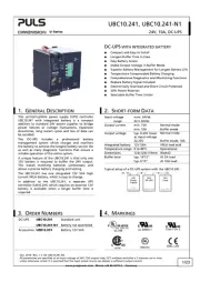
Typical setup of a DC-UPS system with the UBC10.241:
24V
Power
Supply
UBC10.241
24V
DC-UPS
AC
e.g.:
Dimension
DC
24V
Load
e.g.: PLC
3. ORDER NUMBERS
4. MARKINGS
DC-UPS
UBC10.241
Standard unit
UBC10.241-N1
Battery not assembled
Accessories UZB12.051
Battery 12V 5Ah
IND. CONT. E
Q.
UL 508
UL 60950-1
Class I Div 2
R
182790
CUS
GL
Marine
EMC, LVD
Dez. 2019 / Rev. 1.3 DS-UBC10.241-EN
All parameters are specified at an input voltage of 24V, 10A output load, 25°C ambient and after a 5 minutes run-in time
unless otherwise noted. It is assumed that the input power source can deliver a sufficient output current.
www.pulspower.com Phone +49 89 9278 0 Germany
UBC10.241, UBC10.241-N1
USeries
24V, 10A, DC-UPS
Dez. 2019 / Rev. 1.3 DS-UBC10.241-EN
All parameters are specified at an input voltage of 24V, 10A output load, 25°C ambient and after a 5 minutes run-in time
unless otherwise noted. It is assumed that the input power source can deliver a sufficient output current.
www.pulspower.com Phone +49 89 9278 0 Germany
2/23
INDEX PAGE INDEX PAGE
1.
General Description ............................................1
2. Short-form Data ..................................................1
3. Order Numbers....................................................1
4. Markings..............................................................1
5. Input ....................................................................3
6. Output in Normal Mode .....................................4
7. Output in Buffer Mode.......................................5
8. Battery Input .......................................................6
9. Buffer Time..........................................................7
10. Efficiency and Power Losses................................8
11. Functional Diagram.............................................8
12. Check Wiring and Battery Quality Tests.............9
13. Relay Contacts and Inhibit Input......................10
14. Front Side User Elements ..................................12
15. Terminals and Wiring........................................13
16. Reliability ...........................................................13
17. EMC ................................................................... 14
18. Environment ..................................................... 15
19. Protection Features .......................................... 15
20. Safety ................................................................ 16
21. Approvals.......................................................... 16
22. Fulfilled Standards............................................ 16
23. Used Substances ............................................... 17
24. Physical Dimensions and Weight ..................... 17
25. Installation Notes ............................................. 18
26. Replacement of the battery............................. 19
27. Accessories ........................................................ 20
28. Application Notes............................................. 21
28.1. Battery Replacement Intervals............... 21
28.2. Parallel and Serial Use............................ 22
28.3. Using the Inhibit Input........................... 23
28.4. Troubleshooting..................................... 23
INTENDED USE
The unit shall only be installed and put into operation by qualified personnel.
This unit is designed for installation in an enclosure and is intended for general use, such as in industrial control,
office, communication, and instrumentation equipment. Do not use this device in aircraft, trains and nuclear
equipment, where malfunctioning of the power supply may cause severe personal injury or threaten human life.
TERMINOLOGY AND ABREVIATIONS
DC-UPS Uninterruptible power supply with DC-Input.
Normal mode Describes a condition where the battery is charged, the input voltage is in range and the output is
loaded within the allowed limits.
Buffer mode Describes a condition where the input voltage is below the transfer threshold level, the unit is
running on battery (buffering) and the output is loaded within the allowed limits.
Charging mode Describes a condition where the battery is being charged, the input voltage is in range and the
output is loaded within the allowed limits.
Inhibit mode Describes a condition where buffering is disabled on purpose by using the inhibit input of the DC-
UPS. (e.g. for service actions, or to save battery capacity)
Buffer time Same as the term “hold-up time”.
T.b.d. To be defined, value or description will follow later.
DISCLAIMER
The information presented in this document is believed to be accurate and reliable and may change without notice.
Some parts of this unit are patent by PULS (US patent No 091662,063, Des. 424,529, …).
No part of this document may be reproduced or utilized in any form without permission in writing from the publisher.


Produkt Specifikationer

Mærke: Puls Dimension
Kategori: UPS
Model: DIMENSION UBC10.241-N1

Har du brug for hjælp?

Hvis du har brug for hjælp til Puls Dimension DIMENSION UBC10.241-N1 stil et spørgsmål nedenfor, og andre brugere vil svare dig