VHF Communications Antennas for General Aviation
Frequency Range: 118-137 MHz
Installation Instructions
Determine the desired mounting location on
the aircraft. Keep in mind that the antenna
should be located at least two feet away from
other antennas and reective surfaces on the
airframe (e.g., vertical stabilizer, landing gear,
etc.). A good electrical connection must exist
between the antenna mounting hardware and
the metal frame or skin of the aircraft.
2.) Composite or Wood Aircraft
Determine the desired mounting location using
the guidelines discussed above. Create a
“ground plane” on the inside of the aircraft skin
by preparing (2) 48 inch long light gage copper
wires perpendicular to each other and
intersecting at their mid point (forming an X).
Strip away insulation at this intersection if using
insulated wire. Locate this on the inside of the
aircraft skin where the antenna will be mounted
externally. Run the wires forward, aft and side to
side along the inside wall and secure in place.
Attach the (X) intersecting point to one of the
antenna’s mounting bolts, making a good
electrical connection. This concept is similar to
a communications antenna which you would see
at an airport terminal building; a vertical radiator
with (4) ground plane “radials” equally spaced
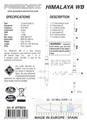
3.) Using the template provided, drill three
mounting holes and one hole for the
Note: Be sure to mount correctly using the
front and rear noted on the template.
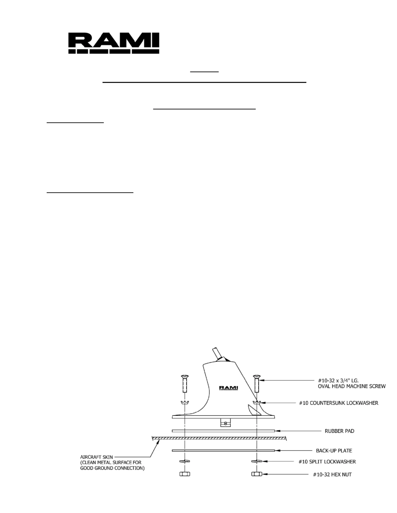
4.) Mount the antenna by placing the rubber pad
provided between the antenna base and
aircraft skin and the back-up plate provided
inside the aircraft. Insert hardware provided as
shown below and tighten all mounting screws
securely to provide good electrical contact.
Caution: The antenna must be properly
grounded by means of the countersunk
through the painted surface under the
5.) Using RG-58/U cable or similar 50 ohm coax
cable (not supplied), attach a BNC type
connector (Delta Electronics #UG-88/U or
equal, not supplied) to one end. See connector
supplier for appropriate mounting instructions.
The other end of the cable must have a
connector attached to match the connector on
6.) Place the cable with the connectors attached
between the antenna and the radio. Test the
antenna by connecting an In-Line Wattmeter
between the transmitter and the antenna.
VSWR should be 3.0 to 1.0 or better for
Rev.: D Revised: January 2019