Reloop RMX-44BT Manual

Reloop DJ udstyr RMX-44BT

Læs gratis den danske manual til Reloop RMX-44BT (4 sider) i kategorien DJ udstyr. Denne vejledning er vurderet som hjælpsom af 6 personer og har en gennemsnitlig bedømmelse på 4.3 stjerner ud af 3.5 anmeldelser. Har du et spørgsmål om Reloop RMX-44BT, eller vil du spørge andre brugere om produktet?

Side 1/4
CAUTION! For your own safety, please read this operation manual carefully before initial operation! All persons
involved in the installation, setting-up, operation, maintenance and service of this device must be appropriately
qualified and observe this operation manual in detail. This product complies with the requirements of the appli-
cable European and national regulations. Conformity has been proven. The respective statements and documents
are deposited at the manufacturer.
Congratulations on purchasing your Reloop RMX44
BT
mixing console. Thank you for placing your trust in our disc jockey
Please remove the Reloop RMX44
BT
from its packaging. Check before initial operation to make sure that the device has
not been visibly damaged during transport. If you detect any damage to the power cable or the casing, do not operate the
device. Contact your specialised dealer.
SAFETY INSTRUCTIONS
CAUTION! Please exercise particular caution when handling AC 100 - 240 V, 50/60Hz power voltage. This voltage
rating may lead to a critical electrical shock! Any damage caused by the non-observance of this operation
manual excludes any warranty claims. The manufacturer is not liable for any damage to property or for personal
injury caused by improper handling or non-observance of the safety instructions.
- This device left the factory in perfect condition. To maintain this condition and to ensure a risk-free operation the user
must observe the safety instructions and warnings contained in this operation manual.
- For reasons of safety and certication (CE) the unauthorised conversion and/or modication of the device is prohibited.
Please note that in the event of damage caused by the manual modication to this device any warranty claims are
excluded.
- The inside of the device does not contain any parts which require maintenance, with the exception of wear parts that
can be exchanged from the outside. Qualied staff must carry out maintenance, otherwise the warranty does not apply!
- The fuse must exclusively be exchanged against fuses of the same class, with the same trigger features and nominal
current rating.
- Ensure that the power will only be supplied after the device has been fully set up. Always plug in the mains plug last.
Ensure that the mains switch is in the “OFF” position when connecting the device to power.
- Only use cables that comply with regulations. Observe that all jacks and bushes are tightened and correctly hooked up.
Refer to your dealer, if you have any questions.
- Ensure that when setting up the product, the mains cable is not squashed or damaged by sharp edges.
- Prevent the mains cable from coming into contact with other cables! Exercise great care when handling mains cables
and connections. Never touch these parts with wet hands!
- Connect the power cable exclusively to appropriate shock-proof outlets. The only supply point to be used is a supply
outlet in accordance with specications of the public supply network.
- Disconnect the device from the supply outlet when not in use and before cleaning! Be sure to hold the mains plug by
the body. Never pull the mains cord!
- Position the device on a horizontal and stable low-ame base.
- Avoid any concussions or violent impact when installing or operating the device.
- When selecting the location of installation, make sure that the device is not exposed to excessive heat, humidity and dust.
Be sure that no cables lie around openly. You will endanger your own safety and that of others!
- Do not rest any containers lled with liquid that could easily spill onto the device or in its immediate vicinity. If, however,
uids should access the inside of the device, immediately disconnect the mains plug. Have the device checked by
a qualied service technician before re-use. Damage caused by uids inside the device is excluded from warranty.
- Do not operate the device under extremely hot (in excess of 35° C) or extremely cold (below 5° C) conditions. Keep the
device away from direct exposure to the sun and heat sources such as radiators, ovens, etc. (even during transport in a
closed vehicle). Always ensure sufcient ventilation.
- The device must not be operated after being taken from a cold environment into a warm environment. The condensation
caused hereby may destroy your device. Do not switch on or operate the device until it has reached ambient temperature!
- Controls and switches should never be treated with spray-on cleaning agents and lubricants. This device should only be
cleaned with a damp cloth. Never use solvents or cleaning uids with a petroleum base for cleaning.
- When relocating, the device should be transported in its original packaging.
- When starting operation, the crossfaders and volume controls of your amplier must be set to minimum level. Bring
the loudspeaker switches into the “OFF” position. Wait between 8 to 10 seconds before increasing the volume to avoid
damage to loudspeakers and diplexer.
- Devices supplied by voltage should not be left in the hands of children. Please exercise particular care when in the
presence of children.
- At commercial facilities the regulations for the prevention of accidents as stipulated by the organization of professional
associations must be observed.
- At schools, training facilities, hobby and self-help workshops the operation of the device must be monitored with
responsibility by trained staff.
- Keep this operation manual in a safe place for later reference in the event of questions or problems.
APPLICATION IN ACCORDANCE
WITH REGULATIONS
- This device is a professional mixing console which can regulate and mix low level audio signals. The device is thereby
connected between a signal source and an audio amplier or active speakers, respectively.
- This product is authorised for connection to 100 - 240 V, 50/60 Hz AC via mains adapter (included) and is designed
exclusively for indoor application.
- If the device is used for any other purposes than those described in the operation manual, damage can be caused to
the product, leading to the exclusion of warranty rights. Moreover, any other application that does not comply with the
specied purpose harbours risks such as short circuit, re, electric shock, etc.
- The serial number determined by the manufacturer must never be removed to uphold the warranty rights.
MAINTENANCE
- Check the technical safety of the device regularly for damage to the mains line or the casing, as well as for wear of wear
parts such as rotary and sliding switches.
- If it is to be assumed that the safe operation is no longer feasible, then the device must be disconnected and secured
against accidental use. Always disconnect the mains plug from the outlet!
- It must be assumed that a safe operation is no longer feasible, if the device bears visible defects, if the device no longer
functions, following longer storage under unfavourable conditions or after major transport stress.
2 2 2 2
5
5
5 5
7 7 7 7
8 8 8 8
6 6 6 6
9
1
111
4
4 4
333
6
13
11
12
22
21
20
19
18
14
15
16
17
23
10
32
24 31 26 25 2728 29 2929 30
29
1. OVERVIEW
1.2 DESIGNATIONS
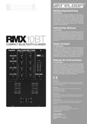
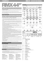
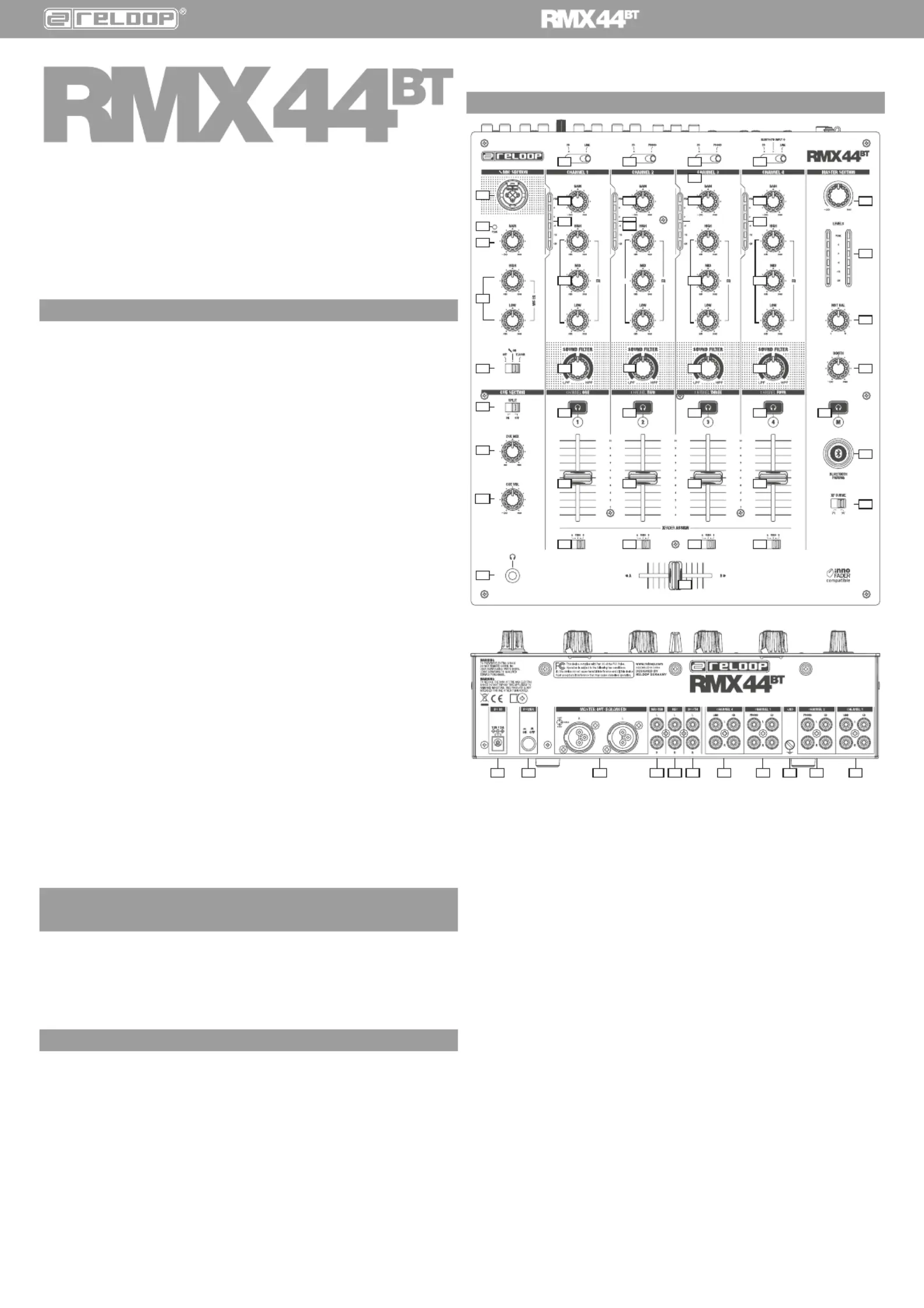
1.2.1................... SIGNAL INPUT CHANNELS
1. ..................... Signal Input Select Switch
2. ..................... Gain Dial
3. ..................... 3-Band Equalizer
4. ..................... Master LEDs
5. ..................... Filter
6. Cue Button .....................
7. ..................... Linefader
8. ..................... Crossfader Assign Switch
9. ..................... Crossfader
10. ..................... Crossfader Curve Switch
1.2.2 ................. MIC CHANNEL
11. ..................... Mic Level
12. ..................... Level Control LED for Mic
13. ..................... 2-Band Equalizer for Mic
14. ..................... Mic Switch
1.2.3 ................. HEADPHONES SECTION
15. ..................... Mono/Stereo Split Select Switch
16. ..................... Cue Mix (Cue/Master Signal Ratio)
17. ..................... Cue Volume (Volume Control Headphones Output)
1.2.4 ................. MASTER SECTION
18. ..................... Master Volume
19. ..................... LED for Master Signal
20. .................... Balance Dial for Master Signal
21. ..................... Booth Volume
1.2.5 ................. CONNECTIONS
22. MIC Input ....................
23. .................... Headphone Out
24. ..................... Power Connection
25. .................... Master Out RCA
26. Master Out XLR (balanced) ....................
27. ..................... Booth Out
28. ..................... Record Out
29. .................... Channel Inputs
30. .................... GND
31. ..................... ON/OFF Switch
32. .................... Bluetooth Button
INSTRUCTION MANUAL
4
3
IMPORTANT NOTE:
(For Mobile Device Conguration)
FCC Radiation Exposure Statement:
This equipment complies with FCC
radiation exposure limits set forth for
an uncontrolled
environment. This equipment should
be installed and operated with
minimum distance 20cm
between the radiator & your body.
IC IMPORTANT NOTE:
(For Mobile Device Conguration)
IC Radiation Exposure Statement:
This equipment complies with IC
RSS-102 radiation exposure limits set
forth for an uncontrolled
environment. This equipment should
be installed and operated with
minimum distance 20cm
between the radiator & your body.
Industry Canada Caution:
This device complies with Industry
Canada licence-exempt RSS
standard(s). Operation is subject to
the following two conditions:
(1) this device may not cause
interference, and
(2) this device must accept any
interference, including interference
that may cause undesired operation
of the device.
1.3 CONNECTING THE RMX44
BT
1.3.1 LINE SIGNALS
Connect your line sources (CD player, tape deck,
controller, etc.) to the corresponding line/CD Channel
Inputs for channels 1 – 4 -29-.
1.3.2 PHONO SIGNALS
Connect your phono sources to the corresponding Phono
Channel Inputs -2- and -3-29-.
Connect your turntables’ grounding cables to the GND
grounding screw -30-.
1.3.3 MICROPHONE SIGNAL
Connect your microphone to the Mic Input -22-.
1.3.4 HEADPHONES
Connect your headphone to the Headphones Out -23-.
1.3.5 MASTER OUTPUT
Connect your sound system to the Master Out -25- (RCA)
or Master Out Balanced XLR (balanced) -26-.
1.3.6 MONITOR OUTPUT
Connect your monitoring system to the Booth Out -27-.
1.3.7 REC OUTPUT
Connect a recording device of your choice to the Record
Out -28-.
The Record Output provides a steady signal, independent
from master signal.
1.3.8 POWER SUPPLY
Connect the power cable to the Power Connection -24-.
Connect the power cable to your power outlet.
2. OPERATION
2.1 POWER ON
After all connections have been carried out, you can turn
on the device via the ON/OFF Switch -31-.
2.2 SIGNAL INPUT SELECT
Via the Signal Input Select Switch -1- you can select
between line and CD sources for channel 1, CD and phono
for channel 2 - 3 and CD, Bluetooth & line sources for
channel 4. Please observe the captions of the single signal
input switches.
2.3 GAIN
Via the Gain Dials -2- you can adjust the input volume for
channels 1 4. Make sure that peak signals stay within
the yellow range of the Master LED indicator -4-.
Use the Mic Level Dial -11- to adjust the microphone.
Make sure that the Mic LED -12- is only lit during signal
peaks.
2.4 EQUALIZER
With the 3 Band Equalizers -3- you can adjust low, mid
and high frequencies for channels 1 – 4.
Via the 2-Band Equalizer -13- you can adjust low and high
frequencies for the MIC Channel.
2.5 FILTER
Channels 1 – 4 dispose of an individual, bipolar lter -5-.
In the 12 o‘clock position the lter is turned off.
When turning clockwise, a highpass effect will be
generated; when turning counter-clockwise a lowpass
effect will be generated.
2.6 LINEFADER
The Linefaders -7- are used to adjust the output volume
for channels 1 – 4.
2.7 CROSSFADER
With the Crossfader -9- it is possible to switch between
the left and right crossfader channel. The crossfader‘s
curve can be adjusted via the Crossfader Curve Switch
-10-. By switching the Crossfader Curve Switch to the
left, it becomes “sharp”, namely good for scratching.
By switching it to the right, the crossfader becomes
“smooth”, namely good for long mixes.
You can use the Crossfader Assign Switch -8- to assign
the crossfader sides A&B to channels 1 – 4.
NOTE! In THRU position no crossfader side is assig-
ned to the respective channel.
2.8 MIC
By using the Mic Switch -14- you can activate the
microphone and, as the case may be, the talkover effect.
This means the suppression of the remaining channels via
the microphone signal (Active Ducking Technology).
In the OFF position the channel is turned off. ON activates
the microphone‘s signal, TLKOVR activates the talkover
function (-18dB).
2.9 MONITORING
With the Cue Buttons -6- you can select the input
channel(s) that you wish to monitor via your headphones.
With Cue Mix -16- you can fade between the channel(s)
selected via the Cue Buttons and the master signal. In the
CUE position you will only hear the monitoring channels
selected via the Cue Buttons; in MASTER position you will
only hear the master signal.
You can mix the signals seamlessly. This way you can
simulate a mix via your headphone. With the Headphone
Input Volume Dial -17- you can adjust your headphone
volume level. Via the Mono/Stereo Switch -15- you can
select the headphone channel‘s output mode.
1.3 ANSCHLIESSEN DES RMX44
BT
:
1.3.1 LINE-SIGNALE
Verbinden Sie Ihre Line-Quellen (CD-Player, Tapedeck,
Controller, etc.) mit den entsprechenden Line/CD-Kanal-
Eingängen für Kanal 1 bis 4 -29-.
1.3.2 PHONO-SIGNALE
Verbinden Sie Ihre Phono-Quellen mit den entsprechenden
Phono-Kanal-Eingängen der Kanäle 2 und 3 -29-.
Verbinden Sie die Erdungskabel Ihrer Plattenspieler mit
der GND-Erdungsschraube -30-.
1.3.3 MIKROFON-SIGNAL
Verbinden Sie Ihr Mikrofon mit der Eingangsbuchse für
das Mikrofon. -22-
1.3.4 KOPFHÖRER-AUSGANG
Verbinden Sie Ihren Kopfhörer mit dem Kopfhörereingäng -23-.
1.3.5 MASTER-AUSGANG
Verbinden Sie Ihre Hauptanlage mit Master Out -25-
(Cinch) oder mit Master Out XLR (symmetrisch) -26-.
1.3.6 MONITOR-AUSGANG
Verbinden Sie Ihre Monitor-Anlage mit Booth Out -27-.
1.3.7 REC-AUSGANG
Verbinden Sie ein Aufnahmemedium Ihrer Wahl mit
Record Out -28-. Der Record Output liefert ein stetiges,
vom Master unabhängiges Signal.
1.3.8 STROMVERSORGUNG
Verbinden Sie das Netzkabel mit dem Stromanschluss
-24-. Schließen Sie das Netzteil an Ihre Steckdose an.
2. BEDIENUNG
2.1 GERÄT EINSCHALTEN
Nachdem alle Anschlüsse vorgenommen wurden, können
Sie das Gerät mit dem ON/OFF Schalter -31- einschalten.
2.2 SIGNAL-EINGANGSWAHL
Mit den Signal-Eingangswahlschaltern -1- können
Sie für Kanal 1 zwischen Line- & CD-, r Kanal 2 - 3
zwischen Line- & Phono- und für Kanal 4 zwischen Line-,
Bluetooth- und CD-Quellen wählen. Beachten Sie dazu die
Beschriftung der einzelnen Signal-Eingangswahlschalter.
2.3 GAIN
Mit den Gain-Reglern -2- wird die Eingangslautstärke für Kanal
1 bis 4 eingestellt. Achten Sie darauf, dass sich das Signal
bei Pegelspitzen maximal im gelben Bereich der LED Anzeige
bewegt -4-. Mit dem Mikrofonlautstärke-Regler -11- wird die
Eingangslautstärke des Mikrofons eingestellt. Achten Sie darauf
dass die Mikrofon-LED -12- nur bei Pegelspitzen leuchtet.
2.4 EQUALIZER
Mit den 3-Band Equalizern -3- nnen die Bässe, Mitten
und Höhen für Kanal 1 bis 4 eingestellt werden.
Mit dem 2-Band Equalizer -13- können die sse und
henr den Mikrofonkanal eingestellt werden.
2.5 FILTER
Die Kale 1-4 verfügen über einen individuellen,
bipolaren Filter -5-. In der 12 Uhr-Stellung ist der Filter
ausgeschaltet. Drehen im Uhrzeigersinn erzeugt einen
Highpass-Effekt, drehen gegen den Uhrzeigersinn erzeugt
einen Lowpass-Effekt.
2.6 LINEFADER
Mit den Linefadern -7- wird die Ausgangslautsrke für
Kanal 1 bis 4 eingestellt.
2.7 CROSSFADER
Mit dem Crossfader -9- wechselt man zwischen
dem linken und dem rechten Crossfader-Kanal. Die
Verlaufskurve des Crossfaders sst sich über den
Crossfader Curve-Schalter -10- einstellen. Die linke
Einstellung macht den Crossfader „scharf“, also gut zum
Scratchen, die rechte Einstellung macht ihn „weich“, was
für langlaufende Mixe geeignet ist. Mit dem Crossfader-
Zuweisungsschalter -8- können Sie den Kanälen 1–4 die
beiden Crossfader-Seiten A&B zuweisen.
HINWEIS! In der Stellung THRU ist dem jeweiligen
Kanal keine Crossfaderseite zugewiesen.
2.8 MIKROFON
Mit dem Mic-Schalter -14- aktivieren Sie das Mikrofon
und ggf. den Talkover-Effekt, d.h. die Unterdrückung
der restlichen Kanäle durch das Mikrofon-Signal (Active
Ducking Technology).
In der OFF-Stellung ist der Kanal ausgeschaltet. ON
aktiviert das Mikrofonsignal, TLKOVR aktiviert die
Talkover-Funktion (-18dB).
2.9 VORHÖREN
Mit den Cue-Tasten -6- wählen Sie den Eingangskanal
oder die Eingangskanäle aus, die Sie im Kopfhörer vorhören
chten. Mit dem Cue Mix -16- können Sie zwischen den/
dem mit den Cue-Schaltern ausgewählten Kanal/Kanälen
und dem Master-Signal überblenden. In der Stellung
„CUE“ hören Sie nur die mit den Cue-Tasten angewählten
Vorhör-Kanäle, in der Stellung MASTER“ hören Sie nur das
Master-Signal. Sie können die Signale stufenlos mischen
und so einen Mix, vorab im Kopfhörer, simulieren. Mit dem
Lautstärkereglerr den Kopfhörereingang -17- stellen Sie
den Lautstärkepegel des Kopfhörers ein. Mit dem Mono/
Stereo-Schalter -15- können Sie den Ausgabemodus für
den Kopfhörerkanal wählen.
1.3 BRANCHEMENT DE LA RMX44
BT
1.3.1 SIGNAUX LINE
Raccorder les sources Line (lecteur de CD, platine
cassette, contrôleur, etc.) aux entrées de canal
respectives Line/CD pour les canaux 1 à 4 -29-.
1.3.2 SIGNAUX PHONO
Raccorder les sources phono aux entes de canal
respectives Phono des canaux 2 et 3 -29-.
Raccorder le ble de terrage de votre platine vinyle aux
vis de terrage GND -30-.
1.3.3 SIGNAL DE MICROPHONE
Raccorder le microphone à la prise d’entrée Mic -22-.
1.3.4 CASQUE
Connectez les écouteurs à la sortie casque -23- .
1.3.5 SORTIE MASTER
Raccorder la chaîne principale à la sortie Master Out -25-
(coaxiale) ou Master Out XLR (Balanced) -26-.
1.3.6 SORTIE MONITOR
Raccorder l’installation de monitorage à Booth Out -27-.
1.3.7 SORTIE REC
Raccorder l’appareil d’enregistrement à la sortie Record
Out -28-. La sortie Record délivre un signal constant
indépendant du Master.
1.3.8 ALIMENTATION ÉLECTRIQUE
Raccorder le câble secteur au branchement secteur -24-.
Brancher la che du ble secteur sur une prise de
courant.
2. UTILISATION
2.1 MISE SOUS TENSION
Après avoir effectué tous les raccords, allumer l’appareil
avec linterrupteur ON/OFF -31-.
2.2LECTION DENTE DU SIGNAL
Avec les sélecteurs d’entrée de signal -1-, vous pouvez
choisir entre les sources ligne et CD pour le canal 1, ligne
et phono pour les canaux 2 - 3 et ligne, Bluetooth et CD
pour le canal 4. Veuillez noter l’étiquetage des différents
sélecteurs d’entrée de signal.
2.3 GAIN
Les régleurs de gain -2- servent à gler le volume
d’entrée pour les canaux 1 à 4. Veiller à ce que le signal
se déplace au plus dans la plage jaune des témoins à DEL
-4-. Le gleur Mic Level -11- servent à régler le volume
d’entrée du microphone . Veiller à ce que le DEL Mic -12-
ne s’allument que lors des pointes.
2.4 ÉGALISEUR
Les égaliseurs à 3 voies -3- servent à régler les graves,
médiums et aigus pour les canaux 1 à 4.
L’égaliseur à 2 voies -13- sert à régler les graves et les
aigus du canal MIC.
2.5 FILTRE
Les canaux 1-4 disposent d’un ltre bipolaire individuel.
-5-
En position 12 heures, le ltre est désactivé.
Tourner à droite pour générer un effet Highpass et à
gauche pournérer un effet Lowpass.
2.6 CURSEUR LINÉAIRE
Les curseurs linéaires -7- servent à régler le volume de
sortie des canaux 1 à 4.
2.7 CROSSFADER
Le Crossfader -9- permet de commuter entre le canal
de Crossfader gauche et droite. Le gleur de courbe
du Crossfader -10- permet de régler la courbe du
Crossfader. Tourner le Crossfader à gauche pour le
„fermer“, ce qui favorise les techniques de Scratching et
de Cutting. Tourner à droit pour le rendre plus „souple“
et ainsi favoriser les enchaînements longs. Le sélecteur
d’affectation du Crossfader -8- permet d’affecter les
canaux 1–4 aux deux côtés A&B du Crossfader .
NOTE ! En position THRU, aucun côté du Crossfader
n’est affecté au canal respectif.
2.8 MIC
La touche Mic -14- permet d’activer le microphone et
le cas échéant, l’effet Talkover, donc la suppression
des autres canaux par le signal du microphone (Active
Ducking Technology).
En position OFF, le canal est désactivé. ON active le signal
du microphone, TALKOVER active la fonction Talkover
(-18dB).
2.9 PRÉ ÉCOUTE
Les touches Cue -6- permettent de sélectionner le canal
ou les canaux d’entrée que vous désirez pré-écouter dans
le casque. Cue Mix -16- sert à enchaîner le canal ou les
canaux sélectionnés avec les touches Cue et le signal
Master ; en position „CUE“, vous entendez seulement
les canaux de p écoute sélectionnés avec les touches
Cue, en position MASTER“ vous entendez seulement le
signal Master. Le régleur de volume pour la sortie casque
-17- vous permet d’ajuster le niveau du volume du casque.
Vous pouvez langer les signaux progressivement.
Vous pouvez simuler préalablement un enchnement
dans le casque. La touche Mono/Stereo -15- permet de
sélectionner le mode de sortie pour le canal du casque.
1.3 CONECTAR LA RMX44
BT
1.3.1 SALES LINE
Conecte las fuentes de línea (reproductor de CD, reproductor
de cintas, controlador, etc.) con las entradas de canal Line/
CD correspondientes para los canales 1 a 4 -29-.
1.3.2 SEÑALES PHONO
Conecte las fuentes Phono con las entradas de canal
Phono correspondientes de los canales 2 y 3 -29-.
Conecte el cable de puesta a tierra de su tocadiscos con
los tornillos de puesta a tierra GND -30-.
1.3.3 SEÑAL DE MICFONO
Conecte el micrófono a la clavija de entrada para el Mic -22-.
1.3.4 AURICULARES
Conecta tus auriculares a la salida de entrada para de
auriculares -23-.
1.3.5 SALIDA PRINCIPAL
Conecte su equipo principal al Master Out -25- (conector
RCA) o al Master Out XLR (Balanced). -26-.
1.3.6 SALIDA DE MONITOR
Conecte su equipo monitor con Booth Out -27-.
1.3.7 SALIDA REC
Conecte el medio de grabación deseado a Record
Out -28-. La salida Record Out proporciona una señal
constante independiente de la principal.
1.3.8 SUMINISTRO DE CORRIENTE
Conecte el cable de red a la toma de corriente -24-.
Conecte el cable de red a su enchufe.
2. MANEJO
2.1. CONECTAR CORRIENTE
Una vez realizadas todas las conexiones, puede conectar
el equipo con el interruptor ON/OFF -31-.
2.2 SELECCIÓN DE ENTRADA DE SAL
Con el selector de entrada de señal -1- se puede elegir
entre fuentes de línea y CD para el canal 1, línea y phono
para el canal 2 - 3 y línea, Bluetooth y fuentes de CD
para el canal 4. Tenga en cuenta el etiquetado de los
interruptores de selección de entrada de señal individual.
2.3 GANANCIA
Con los reguladores de ganancia -2- se ajusta el volumen de
entrada para los canales 1 a 4. Asegúrate de que la señal en
los picos de nivel está dentro del área amarilla de la pantalla
LED -4-. El control de volumen del micrófono -11- ajusta el
volumen de entrada del micrófono. Asegúrate de que el LED
del micrófono -12- sólo se encienda durante los picos de nivel.
2.4 ECUALIZADOR
Con el ecualizador de 3 bandas -3- pueden ajustarse las
frecuencias bajas, medianas y altas para los canales 1 a
4. Con el ecualizador de 2 bandas -13- pueden ajustarse
las frecuencias bajas y altas para el canal MIC.
2.5 FILTRO
Los canales 1-4 disponen de un ltro bipolar individual
-5-. En la posición de 12 horas el ltro esdesconectado.
Al girarlo en el sentido de las agujas del reloj se produce
un efecto high-pass; en el sentido contrario al de las
agujas del reloj un efecto low-pass.
2.6 LINEFADER
Con los linefaders -7- se ajusta el volumen de salida para
los canales 1 a 4.
2.7 CROSSFADER
Con el crossfader -9- se pasa del canal crossfader izquierdo
y el derecho. La curva de progresión del crossfader puede
ajustarse mediante el Interruptor de curva del crossfader
-10-. El ajuste de la izquierda hace que el crossfader sea
„agudo“, es decir, bueno para el rascado, el ajuste de la
derecha lo hace „suave“, lo que es adecuado para mezclas
de larga duración. Con el interruptor de asignación de
crossfaders -8- puedes asignar los dos lados de los
crossfaders A y B a los canales 1-4.
¡AVISO! En la posición THRU el canal correspondiente
no tiene asignado ningún lado del crossfader.
2.8 MIC
Con el interruptor Mic -14- activa el micrófono y, en
caso necesario, el efecto talkover, esto es, la supresión
del resto de canales mediante la señal de micrófono
(Active Ducking Technology). En la posición OFF el canal
está desconectado. ON activa la señal del micrófono;
TALKOVER activa la función talkover (-18dB).
2.9 ESCUCHA PREVIA
Con las teclas Cue -6- selecciona el canal o los canales
de entrada de los que quiere hacer una escucha previa
a través de los auriculares. Con el Cue Mix -16- puede
superponer entre el canal/los canales seleccionados con
los interruptores Cue y la señal principal; en la posición
„CUE escuchará únicamente los canales de escucha
previa seleccionados con los interruptores Cue; en la
posición MASTER escuchará únicamente la señal
principal. Puede mezclar de forma continua las señales.
De esta forma podrá simular previamente una mezcla
en los auriculares. Con el regulador de volumen para la
salida de auriculares -17- ajusta el nivel de volumen de
los auriculares. Con el interruptor Mono/Estéreo -15-
puede seleccionar el modo de reproducción del canal de
auriculares.


Produkt Specifikationer

Mærke: Reloop
Kategori: DJ udstyr
Model: RMX-44BT

Har du brug for hjælp?

Hvis du har brug for hjælp til Reloop RMX-44BT stil et spørgsmål nedenfor, og andre brugere vil svare dig


DJ udstyr Reloop Manualer

Reloop

Reloop RMX-44BT Manual

22 Juli 2025
Reloop

Reloop BeatMix 4 Manual

17 December 2022
Reloop

Reloop BeatMix 2 Manual

17 December 2022
Reloop

Reloop BeatMix Manual

17 December 2022

DJ udstyr Manualer

Nyeste DJ udstyr Manualer