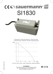
E N Max ow rate 20 l/h @ 50 Hz ( )5.28 gph
Max discharge head 10 m ( )33 ft
Voltage 230 V~50 Hz - 15 W*
Safety switch NC 6 A resistive - 250 V
115 °C ( ) 239 °F auto-reset
Detection levels On: 16 mm, O: 11 mm, Al: 19 mm
On: 5/8”,O: 7/16’’, Al: 3/4’’
Safety standards CE / UL / CSA / EAC / UKCA
Caudal máximo 20 l/h @ 50 Hz ( )5.28 gph
Altura máx. de descarga 10 m ( )33 ft
Tensión 230 V 50 Hz - 15 W* ~
Contacto de alarma NC 6 A resistivo - 250 V
115 °C ( ) 239 °F auto-reset
Niveles de detección On : 16 mm, O : 11 mm, Al : 19 mm
On : 5/8”, O : 7/16’’, Al : 3/4’’
CE / UL / CSA / EAC / UKCA
IT Portata massima 20 l/h
Altezza di mandata massima 10 m
Alimentazione elettrica 230 V 50Hz - 15 W* ~
Contatto di sicurezza NC 6 A resistivo - 250 V
115 °C (riarmo automatico)
Livelli di rilevazione On: 16 mm, O: 11 mm, Al: 19 mm
On: 5/8”, O: 7/16’’, Al: 3/4’’
CE / UL / CSA / EAC / UKCA
Altura de descarga máxima 10 m
Contacto alarme NC 6 A resistivo - 250 V
Níveis de detecção (mm) On : 16, O : 11, Al : 19
Normas de segurança CE / UL / CSA / EAC / UKCA
Zasilanie elektryczne 230 V 50Hz- 15 W* ~
Styk zabezpieczający NC 6 A rezystywny – 250 V
Poziom detekcji (mm) On: 16, O: 11, Al: 19
CE / UL / CSA / EAC / UKCA
Elektrické napájení 230 V 50 Hz- 15 W* ~
Bezpečnostní Kontakt NC odporový - 250 V
Úrovně detekce (mm) On: 16, O: 11, Al: 19
CE / UL / CSA / EAC / UKCA
Débit maximal 20 l/h @ 50 Hz ( )5.28 gph
Hauteur de refoulement max. 10 m ( )33 ft
Contact de sécurité NC 6 A résistif - 250 V
Niveaux de détection Marche : 16 mm, Arrêt : 11 mm,
On : 5/8”, O : 7/16’’, Al : 3/4’’
Normes de sécurité CE / UL / CSA / EAC / UKCA
Stromversorgung 230 V 50 Hz - 15 W* ~
NC 6 A ohmsche Last - 250 V
Überhitzungsschutz 115 °C (automat. Wiederanlauf)
Schaltpunkte (mm) On : 16, O : 11, Al : 19
CE / UL / CSA / EAC / UKCA
Maximale opvoerhoogte 10 m
Stromversorgung 230 V 50 Hz - 15 W* ~
Alarmcontact NC 6 Amp - 250 V
Detectieniveaus (mm) On : 16, O : 11, Al : 19
CE / UL / CSA / EAC / UKCA
Электропитание 230 В ~ 50Гц- 15 Вт*
NC 6 резистивной нагрузки -
Уровни обнаружения(мм) Вкл: 16, Выкл : 11, Авария : 19
CE / UL / CSA / EAC / UKCA
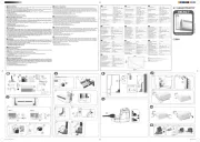
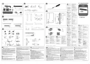
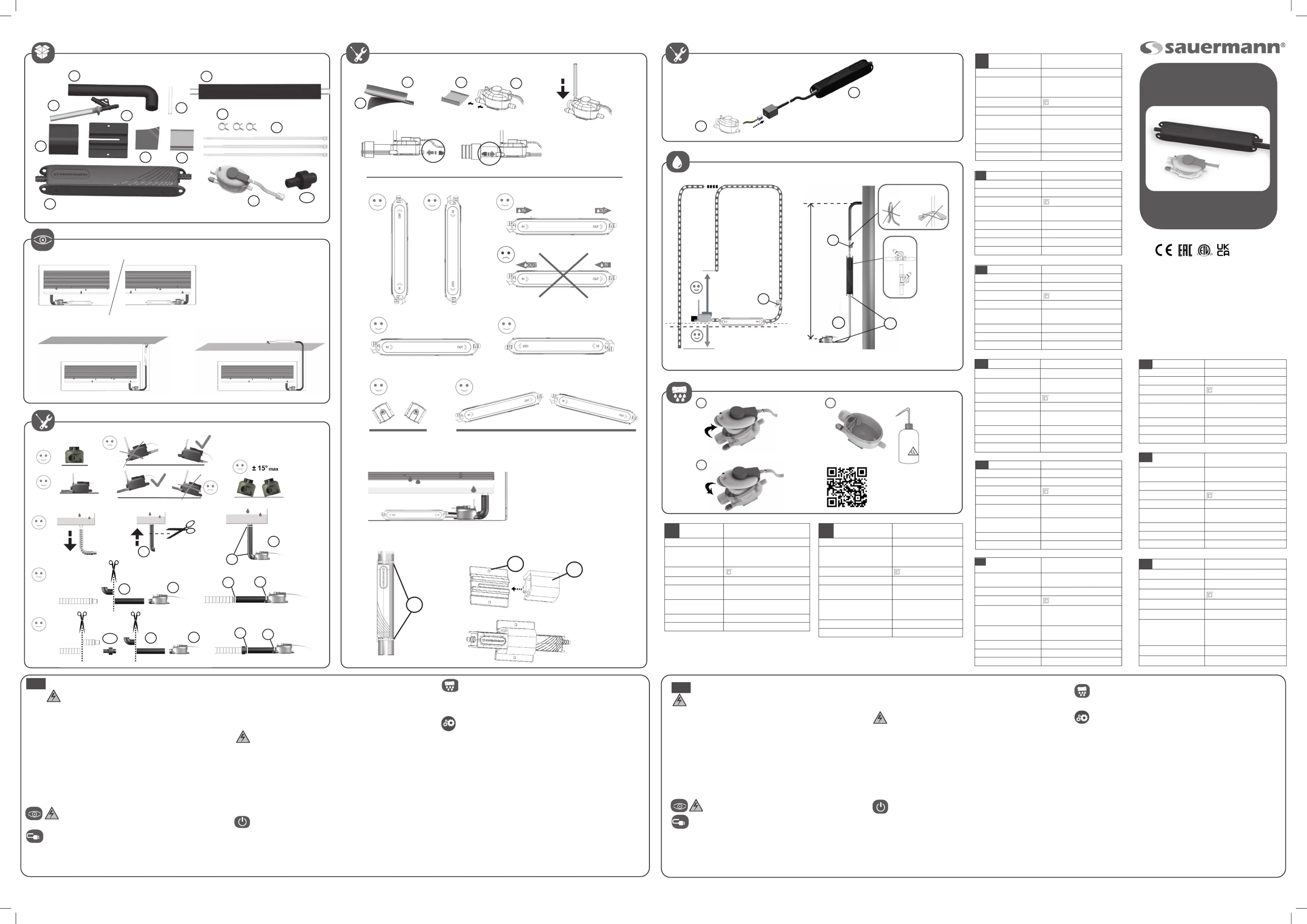
When installed outside the AC unit, the pump must not
be accessible without the aid of a tool.
2 x 0.5 mm² (AWG20) certied UL2464 - 80 °C - 300 V) which must be
fastened securely to the wall, to avoid inadvertent disconnection during
installation and later servicing.
- This connection should be equipped with an electrical isolation device
(2 A Fused Spur, customer provided) to the Phase and Neutral.
The pump must be powered by an electrical circuit protected against
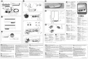
IMPORTANT: Connecting the cable of the safety switch is indispensable
to avoid any risk of overowing. For correct connection, refer to the ap-
The pump is equipped with a NC high water safety switch with a maxi-
mum rating of 6 A/250 V (safety switch CE: 2 x 0.5 mm
(AWG20)).This contact may be used to switch o the air
conditioner where there is a risk of condensate overow (after thorough
verication by the installer of the customer’s specic application and the
resultant electric wiring diagram).
Ensure power cable is not subject to prolonged water exposure.
Risk of electric shock. Make certain that the power
supply to the unit/system is disconnected before attempting to ins-
tall, service or remove any component.
The pump unit must not be immersed in water, installed outside
the premises, stored in a damp environment or exposed to frost.
This pump has not been tested for use in swimming pools or ma-
rine areas.To reduce risk of electric shock, read instruction manual
for proper installation and install the pump and all electrical com-
ponents above the top grade level of the sump.
CAUTION: This pump has been designed for use with water only.
All condensate collection elements (collection tray, connecting
tubes, outlets etc…) must be cleaned thoroughly prior to installing
The pump is supplied with:
- A self-resetting thermal cut-out set at 115 °C (239 °F).
- A self extinguishing body case (UL94 VO Material)
Connect pump Phase and Neutral terminals to the air conditio-
ner unit’s power supply or to the mains supply by means of wiring to
comply with local National Standards. We suggest use of :
- An interconnecting power cable (CE: HO5 VVF 2 x 0.5 mm
- First clean the condensate tray of any debris left over from manu-
facture or unpacking of the air handling unit.
- Pour water into the condensate collection tray (a squeezable plastic
bottle, ACC00401, is available).
- Check that the pump unit starts & then stops as the water level de-
- Check safety switch by continuing to pour water until the alarm trig-
gers (cutting o the compressor).
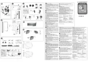
The detection unit requires maintenance and must be clea-
ned at regular intervals in accordance with the degree of pollution
existing within the operating environment.
If the pump doesn’t start, check the wiring and incoming
For all problems rst check:
- the discharge lines are neither obstructed nor kinked,
- the oat inside the detection unit is not blocked
- the hydraulic inlets nor outlets are not obstructed
If the pump is running continuously (>1min), check:
- the discharge height is < 10 m (33 ft)
- the pump is suitable for the capacity of the air conditioning unit,
- while starting the pump, the ow of the water poured into the collection
tray was not too high (ex:1 l in 30 s = 60 l/h >>20 l/h - 1/8 gal in 30 s
If the pump is running continuously and there is no suction of
water, check that the suction hose (hose that connects the pump
and detection unit) is connected and air tight.
If the pump cycles continually or does not shut o:
- check the detection unit is mounted level.
- turn the pump o and see if the water returns down the discharge line. If
water returns down the line you should replace the pump.
Before you start cleaning your air conditioning system, you must remove the
Le bloc de détection doit être nettoyé régulièrment.La
périodicité de ce nettoyage varie en fonction du degré de pol-
lution occasionné par l’environnement.
Pour tout problème, vérier :
- que les tubes ne sont ni obstrués ni pincés,
- que le otteur à l’intérieur du bloc de détection n’est pas bloqué,
- que les entrée et sortie hydrauliques ne sont pas obstruées.
D’autres vérications peuvent être nécessaires.
Si la pompe ne démarre pas, vérier le câblage et l’alimentation
Si la pompe fonctionne trop longtemps (> 1 min), vérier :
- que la hauteur de refoulement est < à 10 m,
- que la pompe est adaptée à la puissance de l’appareil,
- que lors de la mise en service, le débit de l’eau versée n’a pas
été trop important (ex : 1 l en 30 s = 60 l/h >>20 l/h).
Si la pompe fonctionne en continu et n’aspire pas d’eau,
vérier que le tube d’entrée est bien connecté et étanche. Sinon,
Si la pompe enchaîne les cycles sans s’arrêter, vérier :
- que le bloc de détection n’est pas excessivement incliné,
- que, pompe arrêtée, l’eau ne descend pas dans le tube.
Si oui, changer la pompe.
Avant de commencer à nettoyer votre système de climatisation,
veuillez retirer la pompe an d’éviter tout dommage.
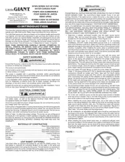
[Instructions originales]
AVERTISSEMENT DE SECURITE
Risque de choc électrique. Avant toute installation,
maintenance ou démontage, mettre impérativement l’ensemble de
l’installation hors tension.
Le bloc pompe ne doit pas être immergé, ni placé à l’extérieur des
locaux ou dans des lieux humides et doit être tenu hors gel. Cette
pompe n’a pas été conçue pour une utilisation dans une piscine ou
ATTENTION : Cette pompe n’est conçue que pour fonctionner
Il est nécessaire de nettoyer les éléments collecteurs de condensats
(bac du climatiseur, tubes, sorties...) avant l’installation de la pompe.
- D’une protection thermique : déclenchement à 115 °C
- D’une enveloppe auto-extinguible (matériau UL94 V0)
Alimentation de la pompe :
Raccorder la phase et le neutre à l’alimentation du climatiseur
ou au réseau par l’intermédiaire de câbles, dans le respect des normes
locales. Nous recommandons l’utilisation :
- D’un câble d’interconnexion (CE : HO5 VVF 2 x 0.5 mm
2 x 0.5 mm² (AWG20) certié UL2464 - 80 °C - 300 V), qui doit être xé
solidement sur le mur pour éviter toute déconnexion involontaire durant
l’installation ou lors de la maintenance.
Test de mise en service :
- Nettoyez le bac de condensats de tout débris (résidus de fabri-
cation ou restes d’emballage).
- Versez un peu d’eau sur la batterie ou dans le bac du climatiseur (utiliser
la burette d’essai ACC00401, non fournie).
- Vériez que la pompe se met en marche et s’arrête lorsque le niveau
- Pour vérier le fonctionnement du contact de sécurité, versez conti-
nuellement de l’eau jusqu’à ce que la sécurité se déclenche (coupure
* En fonction de la référence
- D’un dispositif de protection (disjoncteur 2 A, non fourni) sur la phase et
La pompe doit être alimentée par un circuit électrique protégé contre les
IMPORTANT : Le câblage du contact de sécurité est indispensable pour
éviter tous risques de débordement. Pour un raccordement correct du contact
de sécurité, respecter les indications données par le fabricant du climatiseur.
Pour le raccordement du contact de sécurité, vous disposez d’un contact
NC, d’un pouvoir de coupure 6 A/250 V résistif. (câble d’alarme : CE :
(AWG20)). Ce contact peut être
utilisé pour couper la production frigorique en cas de risque de débor-
dement des condensats (après vérication du schéma électrique et de
l’application client par l’installateur).
Eviter l’exposition prolongée du câble d’alimentation à l’eau.
Lorsqu’elle est installée en dehors du climatiseur, la
pompe ne doit pas être accessible sans l’aide d’un outil.
**SI20UL02UN12 / *** SI20UL02UN23
* SI20CE02UN23 / ** SI20UL02UN12 / *** SI20UL02UN23
液位高度 开泵液位高度 (mm) : 16 mm;
CE / UL / CSA / EAC / UKCA