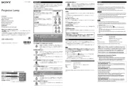
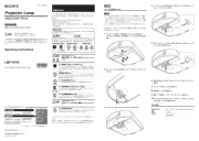
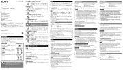
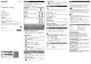
A
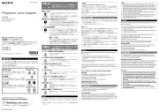
機銘板
Nameplate
Plaque
signalétique
マーク
Mark
Repère
ネジ(
2
本)
Screws (2)
Vis (2)
ネジ(
6
本)
Screws (6)
Vis (6)
レンズアダプター
Lens adapter
Adaptateur d’objectif
スペーサー
Spacer
Entretoise
レンズアダプター部品
Lens adapter parts
Pièces de l’adaptateur
d’objectif
D
ネジ(
3
本)
Screws (3)
Vis (3)
B
マーク
Mark
Repère
ネジ(
6
本)
Screws (6)
Vis (6)
レンズアダプター
Lens adapter
Adaptateur d’objectif
スペーサー
Spacer
Entretoise
電気接点部
Electric connection
Raccordement électrique
E
タッピングネジ(
2
本)
Tapping screws (2)
Vis autotaraudeuses (2)
基板カバー
Substrate cover
Couvercle du substrat
C
モーター部
Motor section
Section moteur
ズームギア
Zoom gear
Engrenages du
zoom
フォーカスギア
Focus gear
Engrenages de la
mise au point
取り付け穴
Attaching hole
Orifice de
fixation
F
モーターカバー
Motor cover
Couvercle du moteur
ネジ(
3
本)
Screws (3)
Vis (3)
日本語
同梱品
レンズアダプター部(
1
)
モーター部(
1
)
基板カバー(
1
)
モーターカバー(
1
)
ネジ
M2
×
6
(
6
)
タッピングネジ
M2
×
6
(
2
)
スペーサー(
2
)
取扱説明書(
1
式)
レンズアダプターの取り付けかた
1
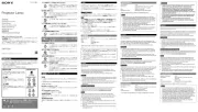
機銘板が上になる状態で、一番上側のネジ穴付近のレンズ本体にマークを付け
る(
-
)。
投写レンズに元から付いているレンズアダプターを外すと、投写レンズの向き
がわからなくなるため、投写レンズにマジックなどでマークを付けます。
2
元から付いているレンズアダプターを固定しているネジ(
6
本)を外し、まっす
ぐに引き抜く(
-
)。
ご注意
外したネジはレンズアダプターを固定する際に使用しますので、なくさない
でください。
レンズアダプターを外すとスペーサーも固定されなくなります。スペーサー
が外れないようにご注意ください。
3
元から付いているレンズアダプター部品(
2
個)を、側面のネジ(
2
本)を外して取
り外す(
-
)。
4
レンズ本体のネジ穴とスペーサーの穴、レンズアダプターのネジ穴の位置を合
わせて、レンズアダプターを突き当たるまで差し込み、手順
1
で書き込んだマー
クと電気接点部を図の位置に合わせて、手順
2
で外したネジ(
6
本)で取り付ける
(
)。
5
モーター部をレンズアダプターの取り付け穴に合わせ、モーター部のギアがレ
ンズ部のズームギアとフォーカスギアにかみ合うようにして(
)、付属のネジ
(
3
本)で取り付ける(
)。
6
モーター部のコネクターを、電気接点部のコネクターに差し込む。
7
基板カバーを、電気接点部の基板を覆うようにして、付属のタッピングネジ
(
2
本)で取り付ける(
)。
8
モーターカバーを、モーター部を覆うようにして、付属のネジ(
3
本)で取り付け
る(
)。
フォーカスが合わない場合は
設置状態によっては、フォーカス調整をしてもフォーカスが合わない場合があり
ます。その場合は、スペーサーの枚数を変えることで調整することができます。
フォーカスリングを時計方向に回しきったときにフォーカスがより合う場合:
スペーサーを
1
枚追加します。
フォーカスリングを時計方向に回しきったときにフォーカスがより合わなくな
る場合:
スペーサーを
1
枚取り外します。
1
投写レンズからレンズアダプターを取り外す。
2
フォーカスの状態に応じてスペーサー
1
枚を追加または取り外す(
)。
予備のスペーサー
2
枚は、レンズアダプターに同梱されています。
If the image is better focused when the focus ring is rotated clockwise all
the way:
Add a spacer.
If the image is less focused when the focus ring is rotated clockwise all the
way:
Remove a spacer.
1 Remove the lens adapter from the projection lens.
2 Add or remove a spacer depending on the focus status (
).
Two spare spacers are supplied with the lens adapter.
3 Attach the adapter to the projection lens.
4 Repeat 1 to 3 until it is in focus.
Note
Depending on the condition of the lens you use, adjustment may be required.
For details concerning adjustments, consult with qualified Sony personnel.
Français
Articles inclus
Section adaptateur d’objectif (1)
Section moteur (1)
Couvercle du substrat (1)
Couvercle du moteur (1)
Vis M2 × 6 (6)
Vis autotaraudeuses M2 × 6 (2)
Entretoises (2)
Mode d’emploi (1 jeu)
Fixation de l’adaptateur d’objectif
1 Placez l’objectif de projection en orientant la partie supérieure de la plaque
signalétique vers le haut et indiquez un repère près de l’orifice de la vis
supérieure de l’objectif (
-).
Puisqu’il est possible que vous ne reconnaissiez pas la position centrale de
l’objectif de projection une fois l’adaptateur d’objectif fixé à l’objectif de
projection retiré, indiquez un repère sur l’objectif de projection à l’aide d’un
feutre, etc.
2 Retirez les six vis de fixation de l’adaptateur d’objectif fixé, puis faites-le glisser
tout droit pour l’extraire (
-).
Remarques
Les vis retirées vont servir à stabiliser l’adaptateur d’objectif : ne les perdez pas.
Une fois l’adaptateur d’objectif retiré, la section entretoise est également
desserrée. Veillez à ce que l’entretoise ne se détache pas.
3 Retirez la partie fixée de l’adaptateur d’objectif (2) en enlevant les vis latérales
(2) (
-).
4 Tout en alignant les positions respectives de l’orifice de vis de l’objectif, de
l’orifice de l’entretoise et de l’orifice de l’adaptateur d’objectif, insérez
l’adaptateur d’objectif à fond jusqu’à ce qu’il s’enclenche. Tout en alignant le
repère indiqué à l’étape 1 sur la partie raccordement électrique du point
illustré, fixez les vis (6) retirées à l’étape 2 (
).
5 Tout en alignant les positions respectives de la section moteur et de l’orifice
de fixation de l’adaptateur d’objectif, enclenchez les engrenages de la section
moteur avec les engrenages du zoom et les engrenages de la mise au point
(
), puis fixez la section moteur à l’aide des vis (3) fournies (
).
3
投写レンズにアダプターを取り付ける。
4
フォーカスが合うまで、手順
1
〜
3
を繰り返す。
ご注意
お客様のご使用されているレンズの状況により、調整が必要になる場合がありま
す。調整については、お買い上げ店またはソニーの相談窓口にご相談ください。
English
Included items
Lens adapter section (1)
Motor section (1)
Substrate cover (1)
Motor cover (1)
Screws M2 × 6 (6)
Tapping screws M2 × 6 (2)
Spacers (2)
Operating Instructions (1 set)
Attaching the Lens adapter
1 Place the projection lens with the upper side of the nameplate facing upward
and place a mark close to the top screw hole on the lens (
-).
Since you may not recognize the center position of the projection lens after
the lens adapter that is attached to the projection lens is removed, place a
mark on the projection lens with a marking pen, etc.
2 Remove the six screws that secure the attached lens adapter then slide it
straight out to remove (
-).
Notes
The removed screws will be used to stabilize the lens adapter, so do not
lose them.
When the lens adapter is removed, the spacer section is also loosened. Be
careful that the spacer is not removed.
3 Remove the attached lens adapter part (2) by removing the side screws (2)
(
-).
4 By matching the positions of the screw hole of the lens, the spacer’s hole, and
the lens adapter’s hole, insert the lens adapter all the way until it is securely in
place. By matching the mark that is placed on Step 1 with the electric
connection part in the illustrated point, attach the screws (6) removed in Step
2 (
).
5 By matching the positions of the motor section and the lens adapter’s
attaching hole, engage the gear of the motor section with the lens zoom gear
and focus gear (
), and attach the motor section using the supplied screws
(3) (
).
6 Insert the connector of the motor section to the connector of the electric
connection section.
7 Attach the substrate cover using the supplied tapping screws (2) overlaying
the electric connection section’s substrate (
).
8 Attach the motor cover using the supplied screws (3) overlaying the motor
section (
).
When the focus cannot be adjusted
According to the installation conditions, the focus may not be adjusted although
the focus adjustment is performed. In this case, adjust the focus by changing the
number of spacers.
6 Insérez le connecteur de la section moteur dans le connecteur de la section de
raccordement électrique.
7 Fixez le couvercle du substrat à l’aide des vis autotaraudeuses (2) fournies
recouvrant le substrat de la section de raccordement électrique (
).
8 Fixez le couvercle du moteur à l’aide des vis (3) fournies recouvrant la section
moteur (
).
Lorsque la mise au point ne peut pas être ajustée
Selon les conditions d’installation, la mise au point peut ne pas être ajustée
même si son réglage est effectué. Dans ce cas, ajustez la mise au point en
modifiant le nombre d’entretoises.
Si la mise au point de l’image est meilleure lorsque la bague de mise au
point est tournée à fond dans le sens horaire :
Ajoutez une entretoise.
Si la mise au point de l’image est moins bonne lorsque la bague de mise au
point est tournée à fond dans le sens horaire :
Retirez une entretoise.
1 Retirez l’adaptateur d’objectif de l’objectif de projection.
2 Ajoutez ou retirez une entretoise en fonction de l’état de la mise au point (
).
Deux entretoises de rechange sont fournies avec l’adaptateur d’objectif.
3 Fixez l’adaptateur à l’objectif de projection.
4 Recommencez les étapes 1 à 3 jusqu’à l’obtention de la mise au point.
Remarque
Un réglage peut s’imposer, selon l’état de l’objectif utilisé. Pour plus
d’informations sur les réglages, consultez un technicien Sony qualifié.
For the customers in the U.S.A.
SONY LIMITED WARRANTY - Please visit http://www.sony.com/psa/warranty
for important information and complete terms and conditions of Sony’s limited
warranty applicable to this product.
For the customers in Canada
SONY LIMITED WARRANTY - Please visit http://www.sonybiz.ca/pro/lang/en/
ca/article/resources-warranty-product-registration for important information
and complete terms and conditions of Sony’s limited warranty applicable to
this product.
For the customers in Europe
Sony Professional Solutions Europe - Standard Warranty and Exceptions
on Standard Warranty. Please visit http://www.pro.sony.eu/ warranty for
important information and complete terms and conditions.
For the customers in Korea
SONY LIMITED WARRANTY - Please visit http://bpeng.sony.co.kr/handler/
BPAS-Start for important information and complete terms and conditions of
Sony’s limited warranty applicable to this product.
Pour les clients au Canada
GARANTIE LIMITÉE DE SONY - Rendez-vous sur http://www.sonybiz.ca/pro/
lang/en/ca/article/resources-warranty-product-registration pour obtenir les
informations importantes et l’ensemble des termes et conditions de la garantie
limitée de Sony applicable à ce produit.